Method for manufacturing a wind turbine blade, a wind turbine blade manufacturing facility, wind turbine blades and uses hereof

a manufacturing facility and wind turbine technology, applied in the field of wind turbine blade manufacturing facilities, can solve the problems of reducing the aerodynamic qualities of the blade, reducing the weight of the blade, and affecting the performance of the blade, so as to achieve the effect of reducing the weight of the blade, and maintaining the shap

Active Publication Date: 2006-08-24
VESTAS WIND SYST AS
View PDF9 Cites 50 Cited by
  • Summary
  • Abstract
  • Description
  • Claims
  • Application Information

AI Technical Summary

Benefits of technology

[0015] It is advantageous to provide the wind turbine blade with a strengthening member in form of e.g. a beam, a web or a latticework, in that one or more members connecting the first wind turbine blade part and the second wind turbine blade part transversely, provides for a very weight efficient way of strengthening the blade. Furthermore the one or more strengthening members may help the blade maintaining its shape.
[0016] Generally it can be said, that the more complicated the wind turbine blades structure is e.g. in form of a many and / or complicated strengthening members, the more advantageous it is, that the compression force can be distributed evenly and that it can be regulated easily.

Problems solved by technology

All of these methods have that serious drawback the pressure is only applied in certain points, providing the joints between the two blade halves with a wave like shape as illustrated on FIG. 2B.
This wave like shape is unwanted, in that it reduces the blades aerodynamic qualities and the joints are provided with a build-in weakness, in that the joints do not have the same strength throughout the length of the blade.
Furthermore if clamps, straps or the like are used for providing the compressing force, it becomes difficult and time consuming to regulate this force to ensure, that the correct amount of pressure is applied in order to produce a blade with a strong and uniform joint.

Method used


Image

  • Method for manufacturing a wind turbine blade, a wind turbine blade manufacturing facility, wind turbine blades and uses hereof
  • Method for manufacturing a wind turbine blade, a wind turbine blade manufacturing facility, wind turbine blades and uses hereof
  • Method for manufacturing a wind turbine blade, a wind turbine blade manufacturing facility, wind turbine blades and uses hereof

Examples


Embodiment Construction

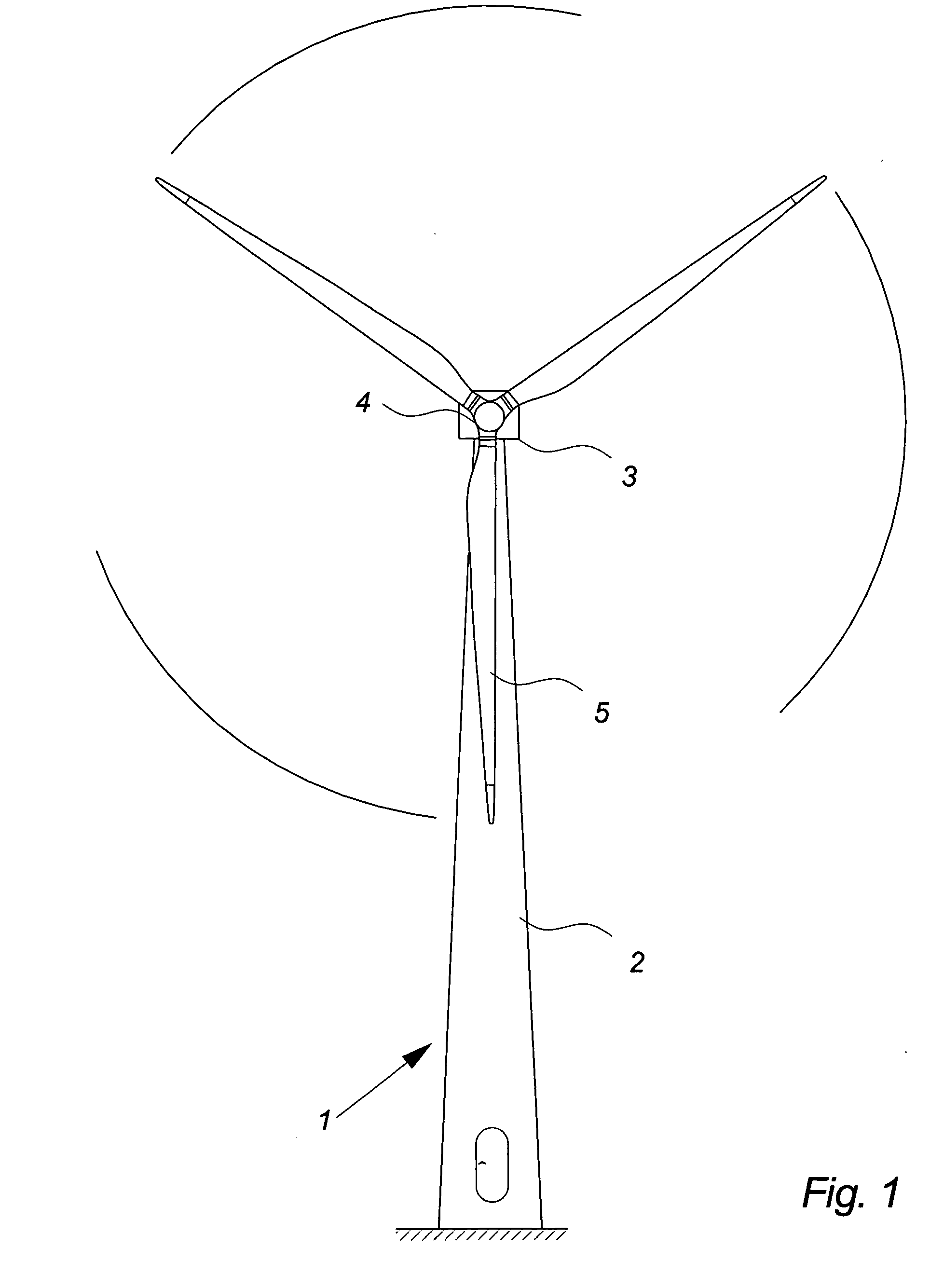
[0106]FIG. 1 illustrates a modern wind turbine 1, comprising a tower 2 and a wind turbine nacelle 3 positioned on top of the tower 2. The wind turbine rotor 4, comprising three wind turbine blades 5, is connected to the nacelle 3 through the low speed shaft which extends out of the nacelle 3 front.

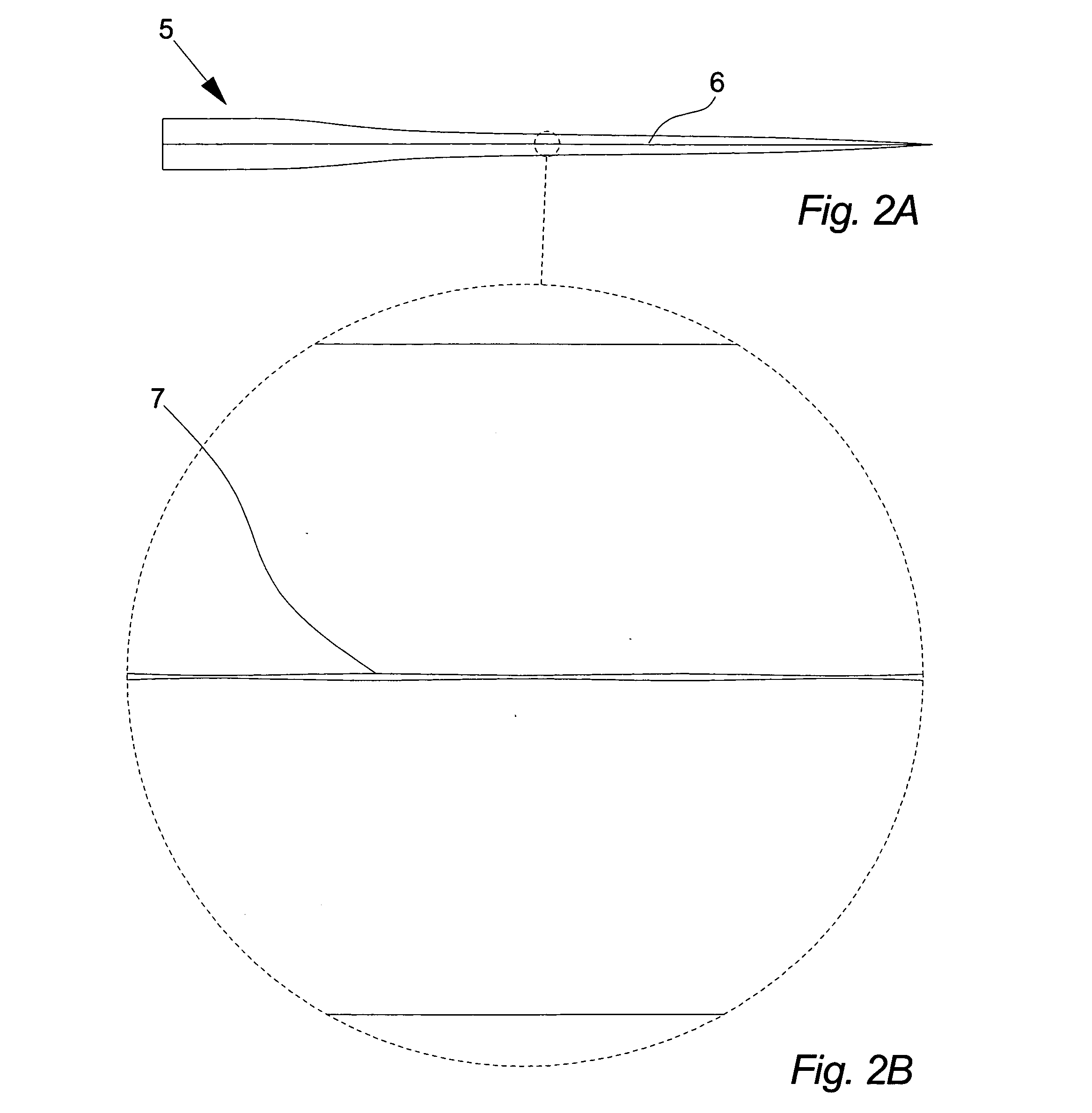
[0107]FIG. 2A illustrates a wind turbine blade 5 as seen from the side. As illustrated a wind turbine blade 5 known in the art is made of two substantially identical blade halves connected in a joint 6 by means of adhesive. To keep the two blade halves pressed firmly together while the adhesive is hardening the known method is to apply pressure to the blade halves, either by means of straps tightened around the halves, by means of hydraulic or pneumatic actuators or other methods applying pressure in a number of specific points.

[0108]FIG. 2B illustrates a section of the same wind turbine blade 5 as illustrated in FIG. 2A, where the wave like shape of the joint 7 is clearly shown.

[0109] ...


PUM

PropertyMeasurementUnit
compressing forceaaaaaaaaaa

Abstract

The invention relates to a method for manufacturing a wind turbine blade or a section of a wind turbine blade. The method includes, establishing a first part having a first wind turbine blade part in a first fixating unit, establishing a second part having a second wind turbine blade part in a second fixating unit, and positioning the first part in contact with, or in close proximity of, the second part. After this, a pressure below atmospheric pressure is established, forcing the first wind turbine blade part and the second wind turbine blade part against each other. The invention further relates to a wind turbine blade manufacturing facility, wind turbine blades as well as uses hereof.

Description

BACKGROUND OF THE INVENTION [0001] The invention relates to a wind turbine blade manufacturing facility, a method for manufacturing a wind turbine blade, wind turbine blades and uses hereof. DESCRIPTION OF RELATED ART [0002] A wind turbine known in the art typically comprises a wind turbine tower and a wind turbine nacelle positioned on top of the tower. A wind turbine rotor, comprising three wind turbine blades, is connected to the nacelle through a low speed shaft, which extends out of the nacelle front as illustrated on FIG. 1. [0003] In resent years the development of mass-produced wind turbines has moved towards making them larger and larger, both in output and in size. This process calls for better and more cost-efficient components and manufacturing methods, and particularly in the field of mass-produced wind turbine blades, this development has been profound, in that the average mass-produced wind turbine blade over the resent years has more than doublet its length. [0004] W...

Claims


Application Information

Patent Timeline
Patent Type & Authority Applications(United States)
IPC IPC(8): B63H1/26
CPCB29C66/1312Y10T29/49339B29C66/721B29C66/82423B29C66/82661B29C69/004B29D99/0028B29L2031/082B29L2031/085F03D1/0675F05B2230/50F05B2230/60Y02E10/721B29C66/543B29C66/636B29C65/48Y10T29/49321Y10T29/49337Y10T29/49336B29C66/54B29C66/7212Y02E10/72Y02P70/50B29C66/61B29C66/524B29C66/131B29C66/112B29C66/532B29K2307/04B29K2309/08
Inventor BECH, ANTONVALSGAARD, POUL
Owner VESTAS WIND SYST AS
Why Eureka
Try Eureka