Osteoimplants and methods for their manufacture

a technology of bone-derived implants and osteo-implants, which is applied in the direction of joint implants, prostheses, surgery, etc., can solve the problems of second-stage damage, difficult to maintain in place, and require preparation

Active Publication Date: 2012-09-18
WARSAW ORTHOPEDIC INC
View PDF242 Cites 56 Cited by
  • Summary
  • Abstract
  • Description
  • Claims
  • Application Information

AI Technical Summary

Benefits of technology

[0010]It is another particular object of the invention to provide a low density osteoimplant which possesses an open pore structure allowing the osteoimplant to readily absorb fluids such as blood and yet still retain its original shape.
[0015]Yet another specific object of the invention is the provision of an osteoimplant in the form of a putty-like material which can be readily molded by the surgeon during a surgical procedure so as to conform to a bone repair site.
[0039]Another particularly useful embodiment of the invention herein is an osteoimplant provided as a coherent aggregate, or matrix, of elongate bone particles possessing an open pore structure and a low bulk density. The open pore structure of the aggregate renders the osteoimplant highly absorbent of surrounding liquids. The osteoimplant formed from the aggregate is flexible when dry (e.g., when containing less than about 6 weight percent water) and does not require time-consuming rehydration prior to implantation. It can assume any desired shape and / or configuration and can be cut to the desired dimensions, e.g., with surgical scissors, before and / or after the aggregate has absorbed fluid. Even in the wetted / hydrated state, the osteoimplant will maintain its original shape and coherency and can be readily handled by the medical practitioner.
[0044]The osteoimplant of the invention car be readily applied to virtually any bore repair site in the body and can be utilized alone or in combination with one or more adjunct medical devices and / or procedures. The osteoimplant of the invention finds particular utility in the areas of dental reconstructive surgery and spinal fusion where substantial amounts of body fluid, e.g., saliva and / or blood, are frequently encountered or where autograft (e.g., local bone, marrow or iliac crest, etc.) is incorporated in the osteoimplant. The unique ability of the osteoimplant to absorb body fluids and still retain its original shape represents a significant advance in the medical field. Additionally, the absorbent nature of the bioimplant encourages the wicking up and recruitment of cells which are essential to osteogenesis.

Problems solved by technology

While effective, it causes secondary damage (to the harvest site) and requires preparation before it can be used.
Furthermore, it is somewhat difficult to maintain in place due to its semi-fluid nature.
The more fluid compositions such as those made with bone powder are relatively easy to implant at the repair site but difficult to maintain in place.

Method used


Image

  • Osteoimplants and methods for their manufacture
  • Osteoimplants and methods for their manufacture
  • Osteoimplants and methods for their manufacture

Examples


example 1

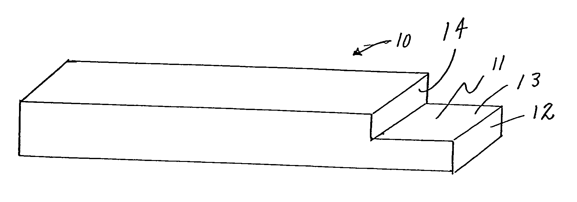
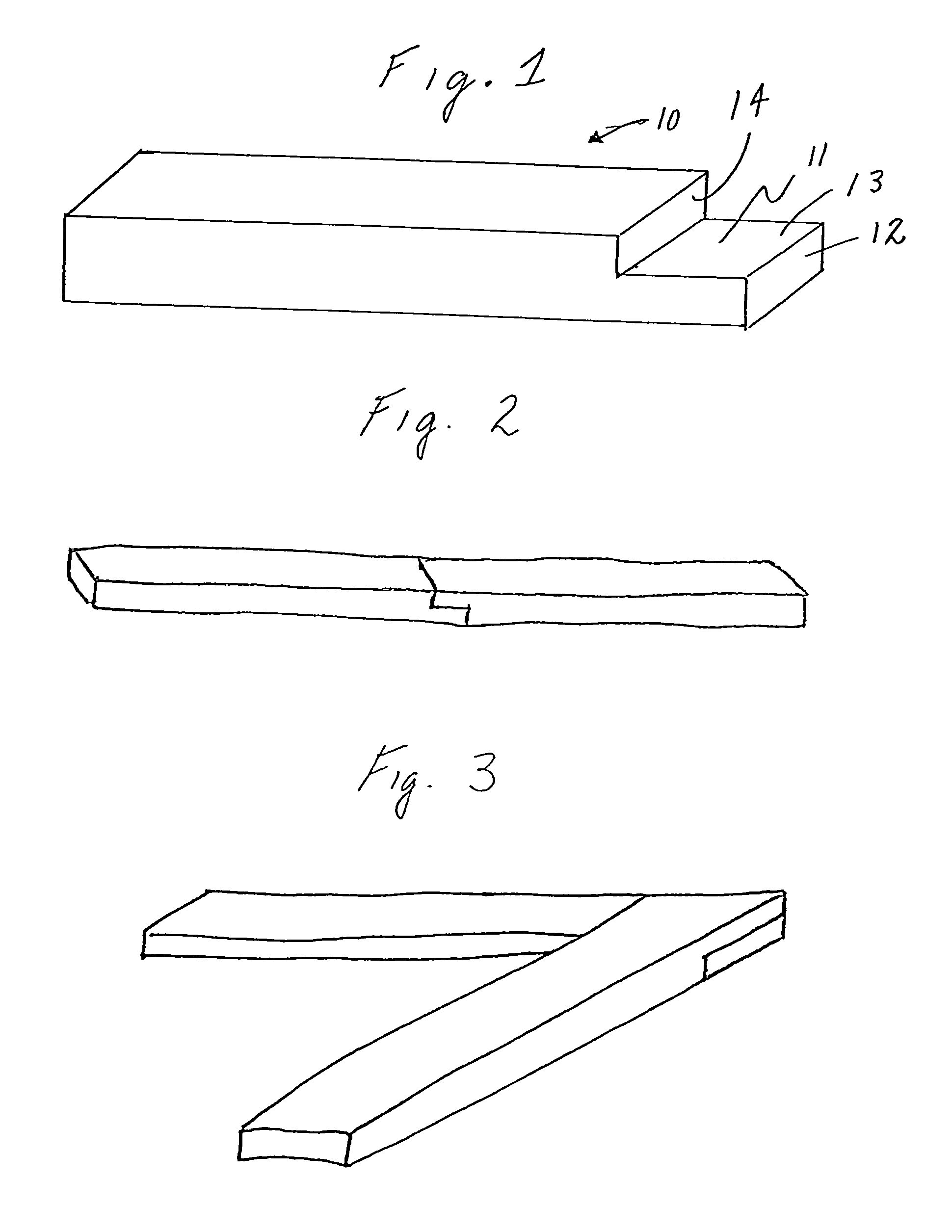
[0083]This example illustrates the preparation of an osteoimplant of the invention in the form of the generally rectangular strip shown in FIG. 1. Osteoimplant 10 possesses a tab 11 of step-like configuration which facilitates combining like strips as shown in FIGS. 2 and 3. Tab 11 includes a first face 12, a flat surface 13 and a second face 14. In general, the osteoimplant can possess a length (inclusive of tab 11) of from about 2 cm to about 50 cm and preferably from about 5 cm to about 20 cm, a width of from about 0.2 cm to about 5 cm, and preferably from about 0.5 cm to about 3 cm, and a depth of from about 0.2 cm to about 2.0 cm, and preferably from about 0.5 cm to about 1.0 cm, with a ratio of length to width of from about 1 to about 5, preferably from about 1 to about 10 and most preferably from about 1 to about 20. Specific dimensions of osteoimplant 10 are a length (inclusive of tab 11) of 10 cm or 20 cm, a width of 1.0 cm, a height of 0.8 cm, a height of 0.4 cm for each o...

example 2

[0086]This example illustrates the preparation of a putty-like, easily moldable osteoimplant composition in accordance with the invention.

[0087]Approximately 200 g to about 300 g of the elongate bone particles used in making the strip-configured osteoimplant of Example 1 are uniformly combined with from about 5 ml to about 15 ml of glycerol per gram of elongate bone particles and from about 5 mls to about 20 ml of distilled deionized water per gram of elongate bone particles to form a slurry which is permitted to swell and hydrate over a period of from 1 to 8 hours. Optionally, prior to either the addition of glycerol, water or both, the elongate fibers may be grated or shredded to reduce any one or more of their overall dimensions. A further optional treatment would be to knead, blend, grind or shred the elongate fibers after the addition of glycerol, water or both. Excess liquid is drained from the slurry and the mixture is thereafter lyophilized under conventional lyophilization ...

example 3

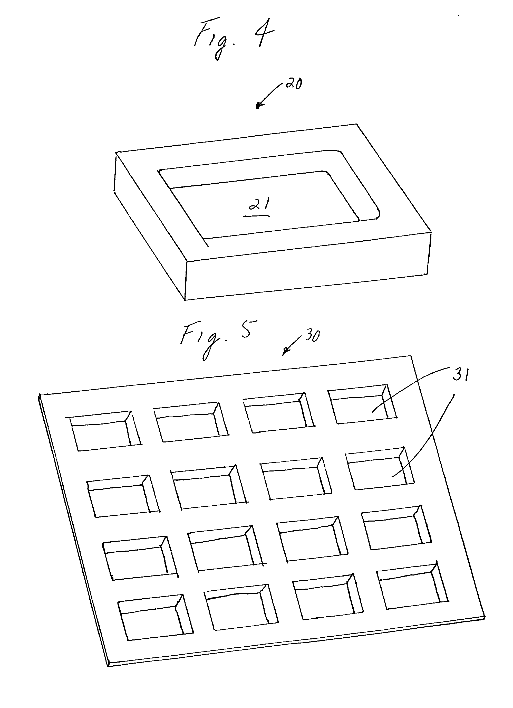
[0088]This example illustrates the manufacture of the trough-like osteoimplant 20 shown in FIG. 4. Osteoimplant 20 possesses a generically rectangular shape and features a trough-like rectangular depression 21. A quantity of such osteoimplants can be conveniently formed using form 30 shown in FIG. 5, cassette 40 shown in FIG. 6 and lid 50 shown in FIG. 7.

[0089]A slurry of swollen, hydrated demineralized elongated bone particles in glycerol and water prepared as described in Example 2 is introduced into cassette 40 of FIG. 6. The perforated base of the cassette permits excess liquid to drain from the slurry. A molding surface in the form of sheet 30 of FIG. 5 having little or no adherency for the slurry and possessing depressions 31 is then impressed upon the exposed surface of the slurry with the application of a gentle amount of pressure so as to provide a molded sheet of substantially uniform thickness (from about 0.5 cm to about 1.0 cm) possessing depressions conforming to the de...


PUM

PropertyMeasurementUnit
densityaaaaaaaaaa
densityaaaaaaaaaa
depthaaaaaaaaaa

Abstract

An osteoimplant is made up of a coherent aggregate of elongate bone particles.

Description

CROSS-REFERENCE TO RELATED APPLICATIONS[0001]This application is a continuation of U.S. application Ser. No. 11 / 297,735, filed on Dec. 8, 2005, which is a continuation of International Patent Application No. PCT / US2004 / 018618, filed on Jun. 10, 2004, which claims the benefit of U.S. Provisional Application No. 60 / 478,130, filed on Jun. 11, 2003, the contents of both applications are incorporated by reference herein.BACKGROUND OF THE INVENTION[0002]1. Field of the Invention[0003]This invention relates to bone-derived implants, or osteoimplants, made up of a coherent aggregate of elongate bone particles and to methods for their manufacture. Among their many applications, the osteoimplants herein can be fashioned in various configurations and sizes for use in repairing bone defects, e.g., as strips for use in spinal fusion procedures, as trough-shaped implants especially useful for PostLateral Fusion (“PLF”) procedures, and as putty-like materials that can be molded on site and packed ...

Claims


Application Information

Patent Timeline
Patent Type & Authority Patents(United States)
IPC IPC(8): A61F2/28A61FA61F2/00A61F2/30A61F2/44A61F2/46
CPCA61F2/28A61F2/4644A61L27/3608A61L27/365A61L27/3658A61L27/38A61L31/005A61F2/4455A61F2002/2817A61F2002/2835A61F2002/30059A61F2002/30075A61F2002/30153A61F2002/30329A61F2002/30593A61F2002/30677A61F2002/30805A61F2002/30957A61F2002/30975A61F2002/4649A61F2210/0061A61F2220/0025A61F2230/0019A61F2310/00293A61F2310/00329A61F2310/00365A61L2430/02A61F2/30A61F2/44
Inventor BETZ, RANDAL R.BODEN, SCOTT D.CLARK, CHRISTINEFORSYTH, NANETTEMORRIS, JOHN W.TRAIANEDES, KATHY
Owner WARSAW ORTHOPEDIC INC
Why Eureka
Try Eureka