
Functional porous film, sensor, method of manufacturing functional porous film, method of manufacturing porous metal film, and method of manufacturing sensor

a technology manufacturing method, which is applied in the field of functional porous film, sensor, method of manufacturing functional porous film, and method of manufacturing porous metal film, can solve the problems of difficult formation of porous metal film with uniform porosity, inability to obtain sufficient characteristics of porous metal film, and inability to uniformly size the pores, etc., to achieve easy control of pores, high precision, and easy control

Inactive Publication Date: 2005-05-26
TDK CORPARATION
View PDF4 Cites 57 Cited by
  • Summary
  • Abstract
  • Description
  • Claims
  • Application Information

AI Technical Summary

Benefits of technology

[0009] It is a second object of the invention to provide a method of manufacturing a porous metal film capable of easily controlling its porosity, its pore size or its pore shape, and a method of manufacturing a sensor using the porous metal film.
[0037] In addition, when the material powder is sintered at a temperature equal to or higher than the thermal decomposition temperature of the organic powder and equal to or lower than the melting point of the material powder, only the surface of the material powder can be slightly molten, and particles of the material powder can be connected to one another in a state where the particle shape is maintained. Therefore, the pore can be controlled with high precision.

Problems solved by technology

Moreover, it is difficult to form a porous metal film with a uniform porosity, a uniform pore size or a uniform pore shape, and, for example, in the method of plating a metal on the core material described in Japanese Unexamined Patent Application Publication No.
Hei 6-240304, there are problems that procedures are complicated, and the porous metal film cannot obtain sufficient characteristics such as conductivity required when the porous metal film is used as an electrode.

Method used


Image

  • Functional porous film, sensor, method of manufacturing functional porous film, method of manufacturing porous metal film, and method of manufacturing sensor
  • Functional porous film, sensor, method of manufacturing functional porous film, method of manufacturing porous metal film, and method of manufacturing sensor
  • Functional porous film, sensor, method of manufacturing functional porous film, method of manufacturing porous metal film, and method of manufacturing sensor

Examples


example 1

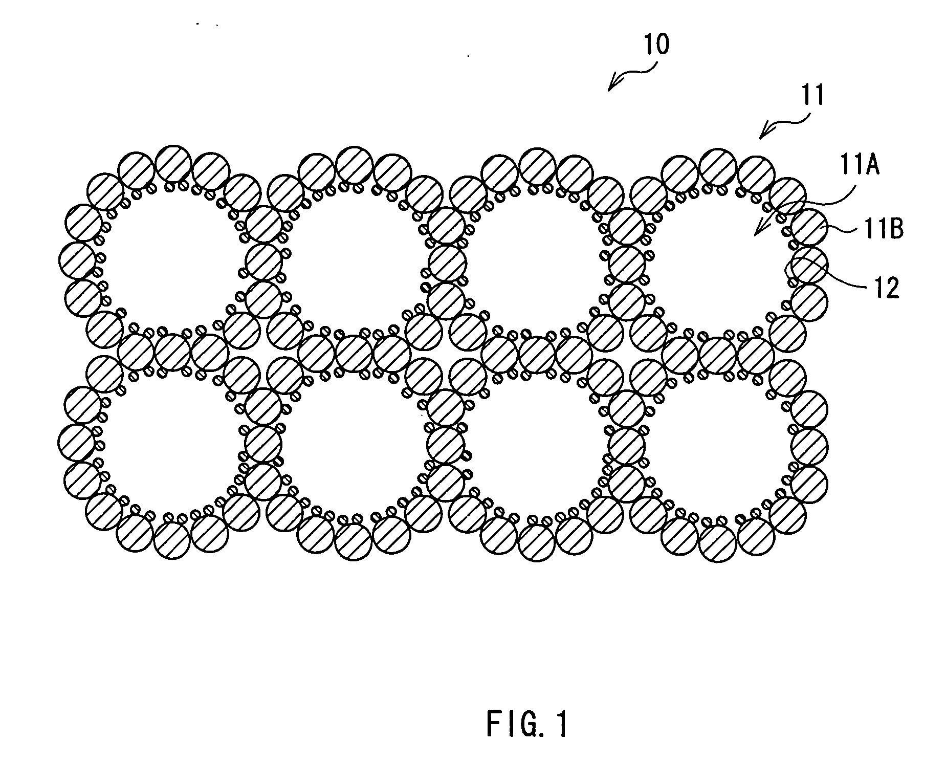
[0160] The functional porous film 10 shown in FIG. 1 was formed through the method shown in FIG. 4. At first, a spherical PMMA powder with an average particle diameter of approximately 10 μm was prepared as the pore-forming powder 21, and a indium oxide powder with an average particle diameter of 0.2 μm was prepared as the functional portion material powder 22. Next, the PMMA powder and the indium oxide powder were mixed and compression bonded by a mixing machine (Mechano Fusion (trademark) manufactured by Hosokawa Micron Corporation) so as to deposit the indium oxide powder on the surface of the PMMA powder. FIG. 14 shows a scanning electron microscope (SEM) photograph of a PMMA particle before the indium oxide powder was deposited, and FIG. 15 shows a SEM photograph of the PMMA particle after the indium oxide powder was deposited. As shown in FIGS. 14 and 15, it was confirmed that the indium oxide powder was deposited on the surface of the PMMA powder.

[0161] Next, a gold powder w...

example 2

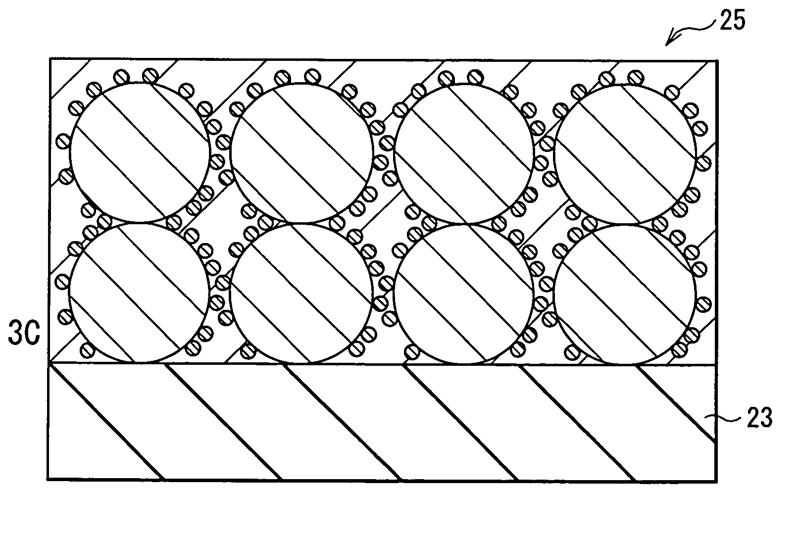
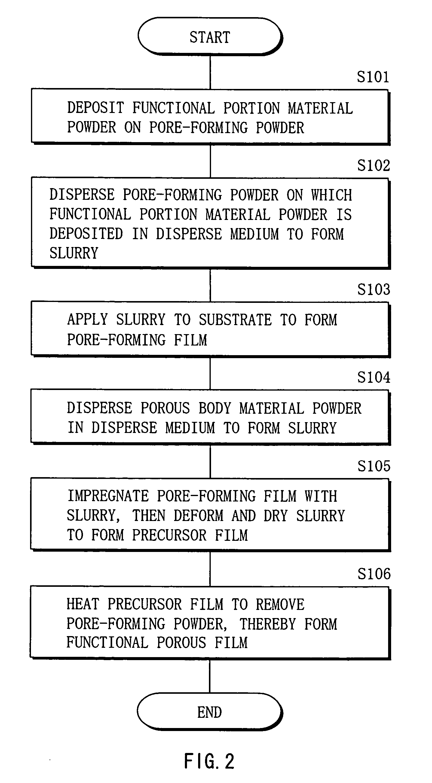
[0168] The functional porous film 10 shown in FIG. 1 was formed through the method shown in FIG. 2. At first, as in the case of Example 1, the PMMA powder and the indium oxide powder were prepared, and the indium oxide powder was deposited on the surface of the PMMA powder. Next, the PMMA powder on which the indium oxide powder was deposited and a dispersant were mixed into water to form slurry. Then, the slurry was applied to a substrate, and was dried to form the pore-forming film 24. Next, a colloidal solution including a gold powder with an average particle diameter of 20 nm was prepared as the slurry, and the slurry was applied to the pore-forming film 24 so as to impregnate the pore-forming film 24 with the slurry, and the slurry was dried. The application of the slurry was repeated several times to form the precursor film 25, and the gold powder was sufficiently spread in the PMMA powder. After that, a two-step firing process in which the precursor film 25 was kept at 400° C....

example 3

[0171] The functional porous film 10 shown in FIG. 1 was formed as in the case of Example 1, except that the method of depositing the functional portion material powder 22 on the pore-forming powder 21 was changed. At first, a spherical PMMA powder with an average particle diameter of approximately 10 μm was prepared as the pore-forming powder 21, and slurry in which an indium oxide powder with an average particle diameter of 20 nm as the material of the functional portion 12 was dispersed was prepared. Next, the slurry of the indium oxide powder was sprayed to the PMMA powder with an injector (Agglomaster (trademark) manufactured by Hosokawa Micron Corporation) to deposit the indium oxide powder on the surface of the PMMA powder. FIG. 18 shows a SEM photograph of a PMMA particle after the indium oxide powder was deposited. As shown in FIG. 18, it was confirmed that the indium oxide powder was deposited on the whole surface of the PMMA powder in film form.

[0172] After the gold powd...


PUM

PropertyMeasurementUnit
sizeaaaaaaaaaa
melting pointaaaaaaaaaa

Abstract

Provided are a functional porous film having a plurality of functions, a method of manufacturing the same, and a sensor using the same. In the functional porous film, a functional portion having a different function from a porous body is disposed on the inner wall of a pore of the porous body. The functional porous film is formed through forming a precursor film including a pore-forming powder such as an organic powder on which a material powder of the functional portion is deposited and a material powder of the porous body, and then heating the precursor film to remove the pore-forming powder and sinter the material powder of the porous body.

Description

BACKGROUND OF THE INVENTION [0001] 1. Field of the Invention [0002] The present invention relates to a functional porous film which can be suitably used for various sensors such as a carbon dioxide sensor, a hydrogen sensor and a nitrogen oxide sensor, a method of manufacturing the functional porous film, a sensor using the functional porous film, a method of manufacturing a porous metal film, and a method of manufacturing a sensor using the porous metal film. [0003] 2. Description of the Related Art [0004] In recent years, porous metal films are used in various technical fields such as sensors. As the porous metal films, for example, a mesh porous metal film and a porous metal film formed through sintering a metal powder are known. As a method of forming a porous metal film through sintering a metal powder, for example, a method in which a metal powder is dispersed in an organic mediu, such as ethylene glycol to form slurry, and a coating of the slurry is applied, then the coating ...

Claims


Application Information

Patent Timeline
Patent Type & Authority Applications(United States)
IPC IPC(8): B22F3/11G01N27/407H01M4/86H01M4/88
CPCB22F3/114B22F2998/00G01N27/4075B22F3/1121B22F3/11
Inventor ONO, SHIZUKOEGASHIRA, MAKOTOSHIMIZU, YASUHIROHYODO, TAKEO
Owner TDK CORPARATION
Learn More