Accommodating intraocular lens with ciliary body activation

a technology of ciliary body and lens body, applied in the field of accommodating lenses, can solve the problems of iol clouding, various degrees of blindness, posterior capsular opacification, etc., and achieve the effect of preventing the movement of the lens body

Inactive Publication Date: 2014-05-01
NOVARTIS AG
View PDF4 Cites 50 Cited by
  • Summary
  • Abstract
  • Description
  • Claims
  • Application Information

AI Technical Summary

Benefits of technology

[0005]According to various implementations of the invention, an accommodative intraocular lens (IOL) is formed having a lens body that is in a disaccommodative configuration (i.e., has a curvature that is in a disaccommodated shape). The lens body is attached, directly or indirectly, to an anatomical structure of an eye such as a ciliary body. In some implementations, the lens body is attached to the ciliary body via a haptic system that includes one or more haptics, which help support and transmit an accommodative force to the lens body. For example, the haptics may transmit an axial compressive force from the ciliary body to

Problems solved by technology

A cataract can occur when the natural lens of an eye or its surrounding transparent membrane becomes clouded, resulting in various degrees of blindness.
Some conventional replacement IOLs are rigid and not intended to flex or provide accommodation and therefore requires the patient to use external vision correction such as

Method used


Image

  • Accommodating intraocular lens with ciliary body activation
  • Accommodating intraocular lens with ciliary body activation
  • Accommodating intraocular lens with ciliary body activation

Examples


Embodiment Construction

[0016]The accompanying drawings, which are incorporated into and constitute a part of this specification, illustrate one or more examples of implementations of the invention and, together with the description, serve to explain various principles and aspects of the invention.

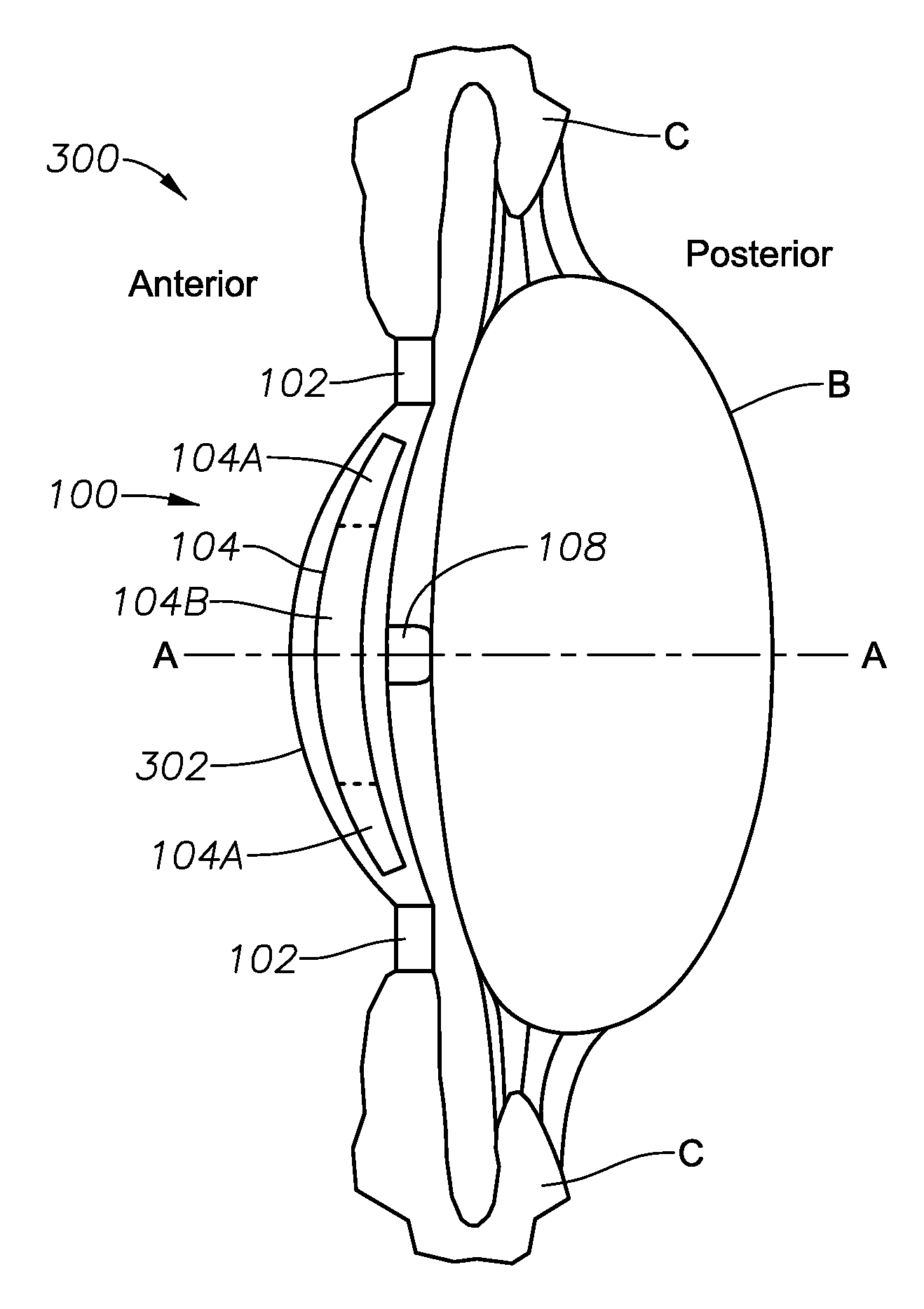
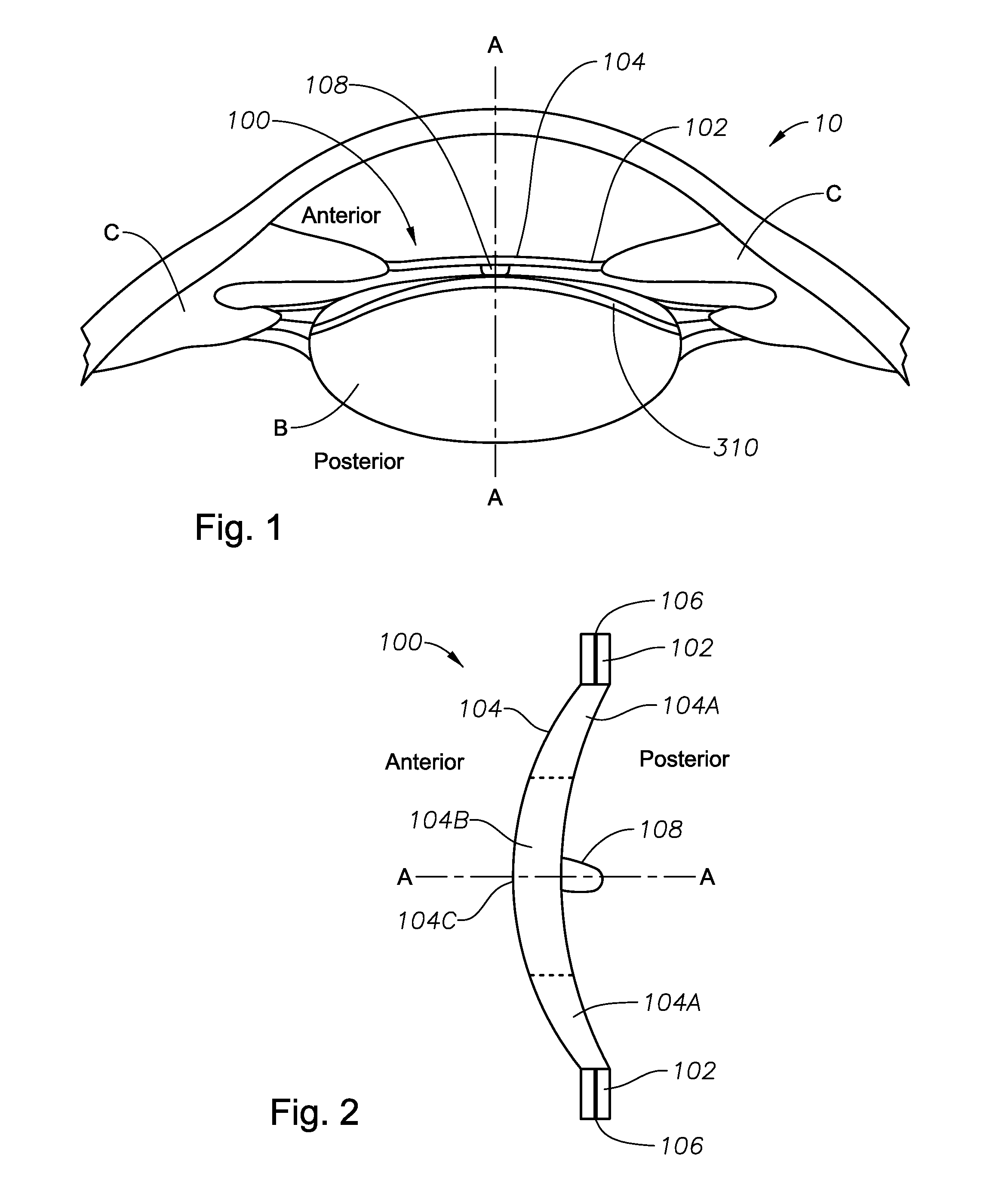
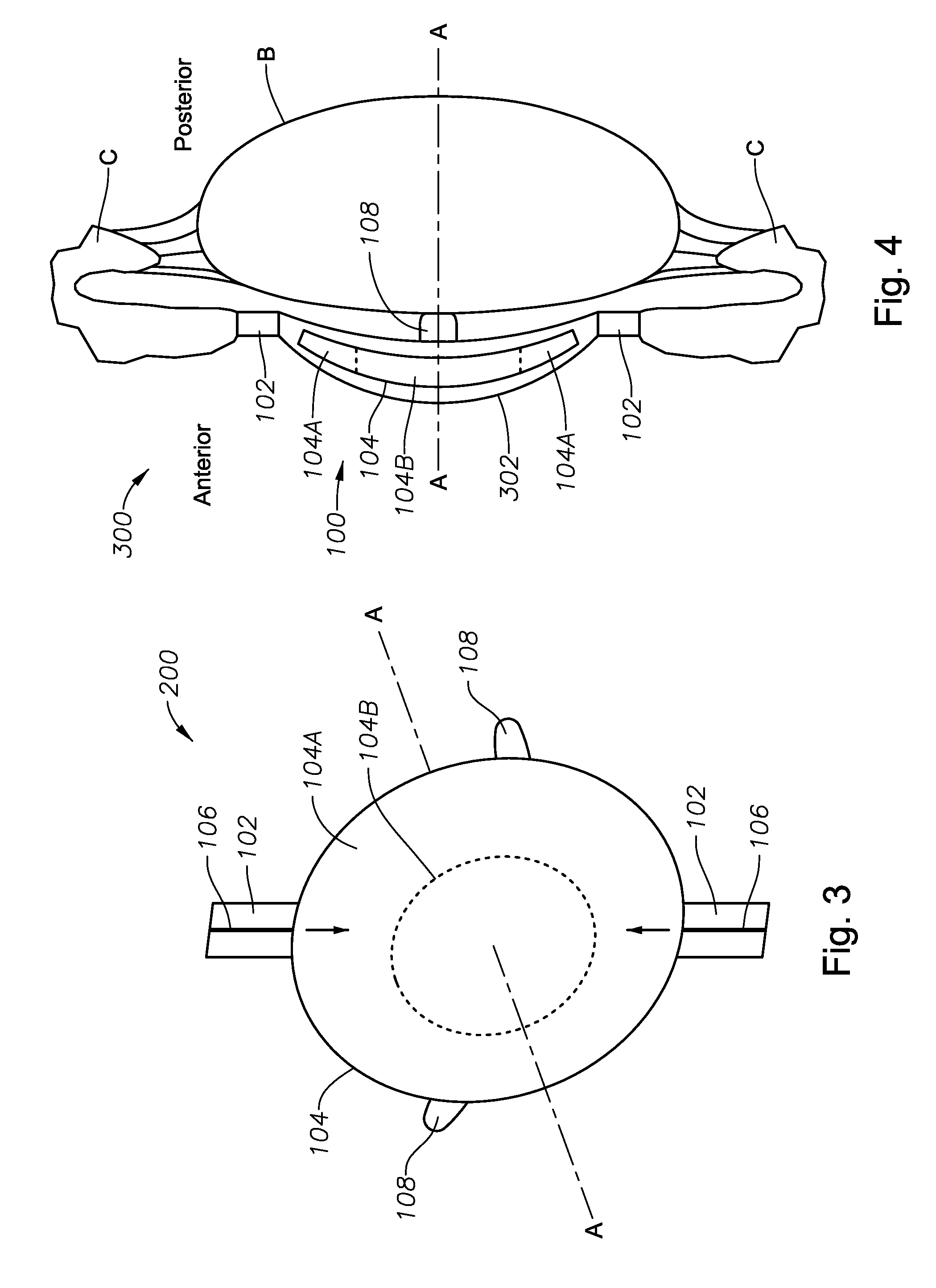
[0017]FIGS. 1-4 illustrate an accommodating lens assembly 100, according to various implementations of the invention. As illustrated in FIG. 2, lens assembly 100 includes a haptic system 102, a lens body 104, and a wing 108. Lens assembly 100 is illustrated with respect to an optical axis A-A that generally runs through the center of lens body 104. As shown in FIG. 1, the lens assembly 100 generally will be implanted within a patient's eye 10 in a position within or in front of the capsular bag B. For example, the lens assembly 100 can be implanted within the anterior chamber A of the patient's eye immediately in front of and / or engaging a forward portion of the capsular bag, with the haptics extending radially o...


PUM


Abstract

An accommodative lens assembly includes a lens body defining an optic lens, a haptic system, and a wing. The lens body is formed and implanted into an eye in a disaccommodative configuration. The haptic system includes one or more haptics that support the optic lens and transmits forces from an anatomical structure such as a ciliary body of the eye, causing the optic lens to deform into an accommodative configuration. In order to stabilize the optic lens so that the optic lens is not displaced from its implantation site, the wing anchors the optic lens within an anterior capsulorhexis of the capsular bag such that the transmitted forces that deform the optic lens during accommodation do not also displace the optic lens from its implanted position. When implanted, the optic lens is anterior to the capsular bag.

Description

[0001]This application claims the priority of U.S. Provisional Patent Application No. 61 / 720,688 filed on Oct. 31, 2012.FIELD OF THE INVENTION[0002]The present disclosure relates to an accommodative lens and in particular to an intraocular lens that accommodates in response to movement by a ciliary body of a patient's eye and is anchored to the capsular bag to prevent displacement of the intraocular lens during accommodation.BACKGROUND OF THE INVENTION[0003]A cataract can occur when the natural lens of an eye or its surrounding transparent membrane becomes clouded, resulting in various degrees of blindness. One method of treating this condition is to perform cataract surgery, which involves removing the cataract and implanting an intraocular lens (“IOL”). Some conventional replacement IOLs are rigid and not intended to flex or provide accommodation and therefore requires the patient to use external vision correction such as eyeglasses or contact lenses for near vision. Other convent...

Claims


Application Information

Patent Timeline
IPC IPC(8): A61F2/16
CPCA61F2/1624A61F2/1648A61F2/1635A61F2002/1699A61F2002/1682
Inventor SIMPSON, MICHAEL J.
Owner NOVARTIS AG
Why Eureka
Try Eureka