Multilayer capacitor and method of adjusting equivalent series resistance of multilayer capacitor

a technology of equivalent series resistance and multilayer capacitor, which is applied in the direction of fixed capacitors, stacked capacitors, fixed capacitor details, etc., can solve the problem of difficult control of equivalent series resistance, and achieve the effect of easy adjustment of equivalent series resistance and high precision

Active Publication Date: 2006-07-27
TDK CORPARATION
View PDF7 Cites 12 Cited by
  • Summary
  • Abstract
  • Description
  • Claims
  • Application Information

AI Technical Summary

Benefits of technology

[0040] The present invention can provide a multilayer capacitor and a method of adjusting an equivalent series res

Problems solved by technology

However, the following problem exists in the multilayer capacitor disclosed in Japanese Patent Application Laid-Open No. 2004-47983 when adjusting the equivalent series resistance to a desirable value.
Namely, for adjusting the equivalent series resistance to a desirable value, the multilayer capac

Method used


Image

  • Multilayer capacitor and method of adjusting equivalent series resistance of multilayer capacitor
  • Multilayer capacitor and method of adjusting equivalent series resistance of multilayer capacitor
  • Multilayer capacitor and method of adjusting equivalent series resistance of multilayer capacitor

Examples


eighth embodiment

[0182] With reference to FIG. 9, the structure of the multilayer capacitor in accordance with an eighth embodiment will now be explained. The multilayer capacitor in accordance with the eighth embodiment differs from the multilayer capacitor C1 in accordance with the first embodiment in terms of the number of first inner electrodes electrically connected to first terminal electrodes 3a to 3d via lead conductors 171 to 174 and the number of second inner electrodes electrically connected to second terminal electrodes 5a to 5d via lead conductors 181 to 184. The multilayer capacitor in accordance with the eighth embodiment also differs from the multilayer capacitor in accordance with the fifth embodiment in terms of positions of the first inner electrodes electrically connected to the first terminal electrodes 3a to 3d via the lead conductors 171 to 174 in the laminating direction and positions of the second inner electrodes electrically connected to the second terminal electrodes 5a t...

ninth embodiment

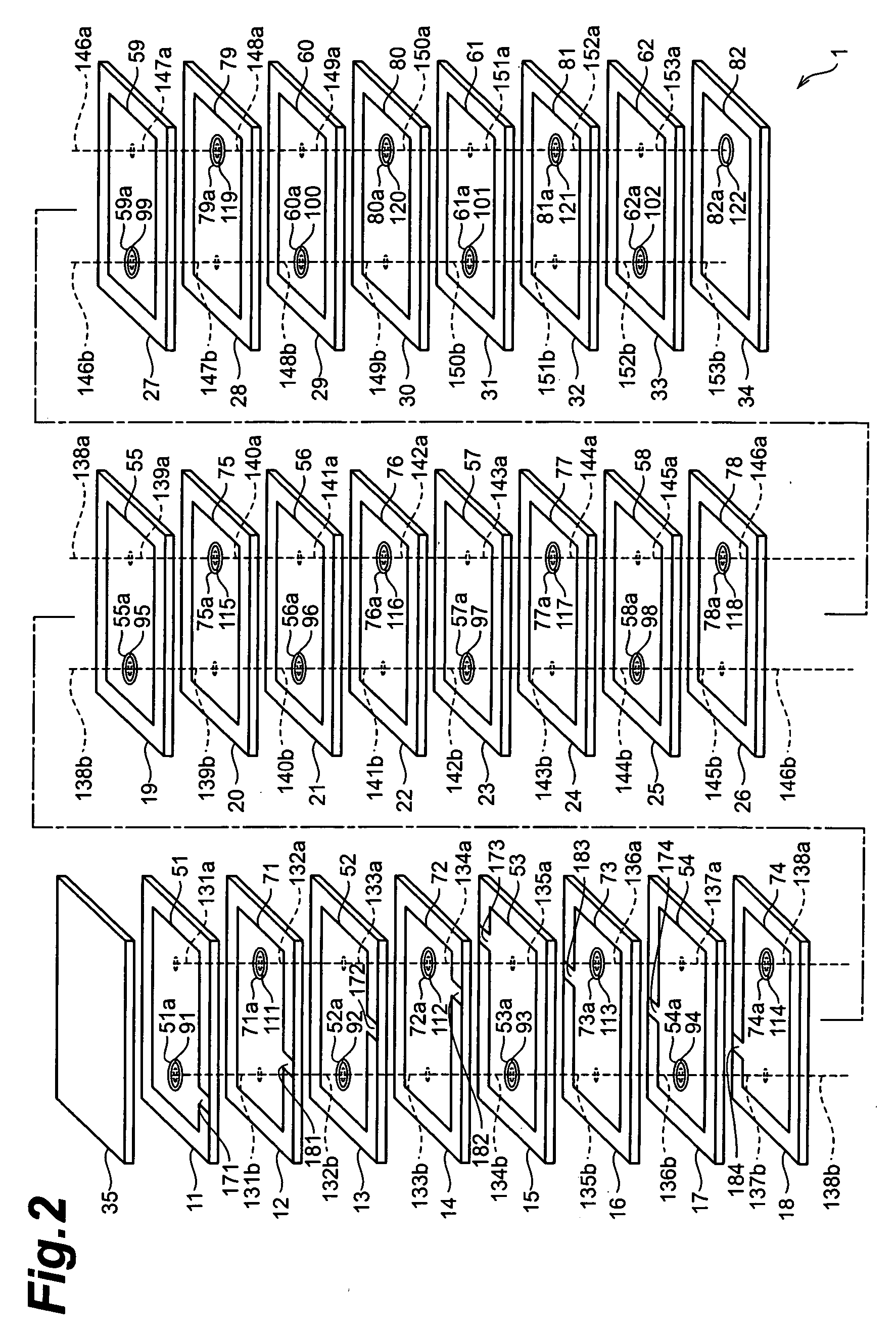
[0188] With reference to FIG. 10, the structure of the multilayer capacitor in accordance with a ninth embodiment will now be explained. FIG. 10 is an exploded perspective view of the multilayer body included in the multilayer capacitor in accordance with the ninth embodiment.

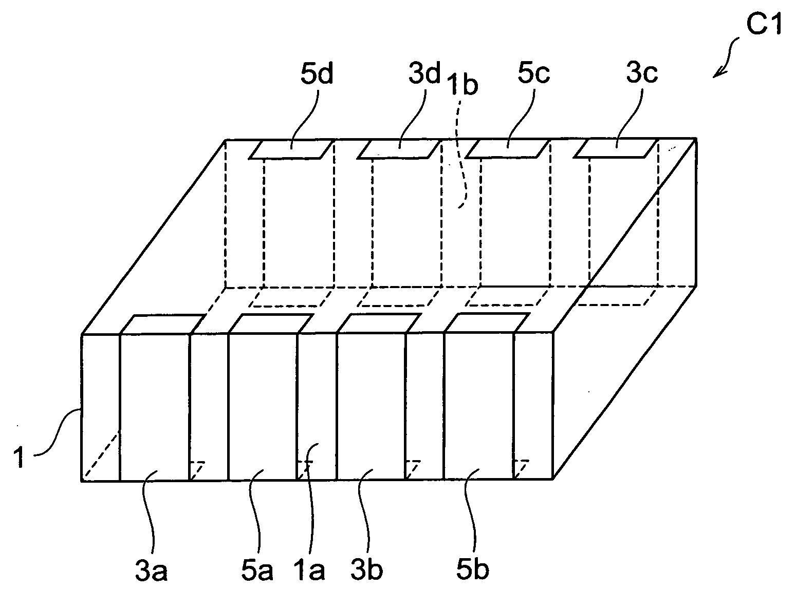
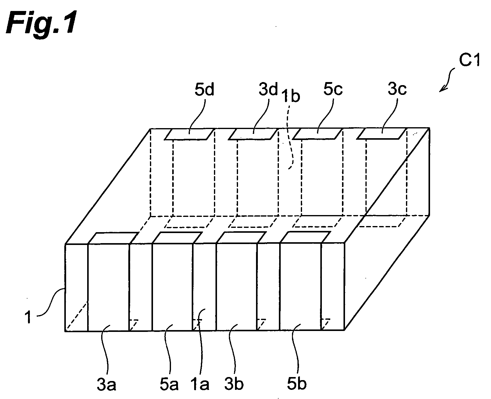
[0189] As with the multilayer capacitor C1 in accordance with the first embodiment, the multilayer capacitor in accordance with the ninth embodiment comprises a multilayer body 1, first terminal electrodes 3a to 3d formed on the multilayer body 1, and second terminal electrodes 5a to 5d similarly formed on the multilayer body 1, though they are not depicted.

[0190] As is also shown in FIG. 10, the multilayer body 1 is constructed by alternately laminating a plurality of (39 in this embodiment) dielectric layers 11 to 49 and a plurality of (19 each in this embodiment) first and second inner electrodes 51 to 69, 71 to 89. In the actual multilayer capacitor, the dielectric layers 11 to 49 are integrated together ...

tenth embodiment

[0204] With reference to FIGS. 11 and 12, the structure of the multilayer capacitor C2 in accordance with a tenth embodiment will be explained. FIG. 11 is a perspective view showing the multilayer capacitor in accordance with the tenth embodiment. FIG. 12 is an exploded perspective view of the multilayer body included in the multilayer capacitor in accordance with the tenth embodiment. The multilayer capacitor C2 in accordance with the tenth embodiment differs from the multilayer capacitor C1 in accordance with the first embodiment in terms of the number of first and second terminal electrodes.

[0205] As shown in FIG. 11, the multilayer capacitor C2 comprises a multilayer body 1, a plurality of (5 in this embodiment) first terminal electrodes 3a to 3e formed on the multilayer body 1, and a plurality of (5 in this embodiment) second terminal electrodes 5a to 5e similarly formed on the multilayer body 1.

[0206] The first terminal electrode 3a is positioned on the side of a side face 1...


PUM


Abstract

A multilayer capacitor comprises a multilayer body in which dielectric layers and inner electrodes are alternately laminated, and terminal electrodes formed on the multilayer body. The inner electrodes include first inner electrodes and second inner electrodes alternately arranged. The terminal electrodes include at least three terminal electrodes. The first inner electrodes are electrically connected to each other via a through-hole conductor. The second inner electrodes are electrically connected to each other via a through-hole conductor. At least two first inner electrodes in the first inner electrodes are electrically connected via a lead conductor to at least two respective terminal electrodes whose number is smaller than the total number of the terminal electrodes by at least 1 in the at least three terminal electrodes. At least one second inner electrode in the second inner electrodes is electrically connected via a lead conductor to the remainder of terminal electrodes other than the terminal electrodes electrically connected to the first inner electrodes via the lead conductor. An equivalent series resistance is set to a desirable value by adjusting the number of at least one species of the first and second inner electrodes electrically connected to the terminal electrodes via the lead conductors.

Description

BACKGROUND OF THE INVENTION [0001] 1. Field of the Invention [0002] The present invention relates to a multilayer capacitor and a method of adjusting an equivalent series resistance of a multilayer capacitor. [0003] 2. Related Background Art [0004] Known as this kind of multilayer capacitor is one comprising a multilayer body in which a plurality of dielectric layers and a plurality of inner electrodes are alternately laminated, and a plurality of terminal electrodes formed on the multilayer body (see, for example, Japanese Patent Application Laid-Open Nos. 2001-185441 and 2004-47983). [0005] Power supplies for central processing units (CPUs) mounted in digital electronic devices have been increasing their load current while lowering their voltage. Therefore, it has become quite difficult to suppress the fluctuation in power supply voltage under a tolerable level in response to a drastic change in load current, whereby a multilayer capacitor known as decoupling capacitor has come in...

Claims


Application Information

Patent Timeline
IPC IPC(8): H01G4/228
CPCH01G4/232H01G4/30E02D5/24E02D27/42E02D2600/30
Inventor TOGASHI, MASAAKIAHIKO, TAISUKE
Owner TDK CORPARATION
Why Eureka
Try Eureka