Multilayer chip capacitor including two terminals

a multi-layer chip and capacitor technology, applied in the direction of capacitors, fixed capacitor details, fixed capacitors, etc., can solve the problems of increasing current consumption, reducing the operating voltage of the mpu chip, and dc supply voltage noise becomes more difficult to suppress, so as to minimize the increase in equivalent series inductance and high equivalent series resistance

Active Publication Date: 2012-06-05
SAMSUNG ELECTRO MECHANICS CO LTD
View PDF10 Cites 11 Cited by
  • Summary
  • Abstract
  • Description
  • Claims
  • Application Information

AI Technical Summary

Benefits of technology

[0008]An aspect of the present invention provides a 2-terminal multilayer chip capacitor that achieves high equivalent series resistance (ESR) while minimizing an increase in equivalent series inductance (ESL).

Problems solved by technology

An operating frequency for a high-speed micro processor unit (MPU) is continuously increasing, leading to an increase in current consumption, and an operating voltage for an MPU chip is being lowered.
Thus, it becomes more difficult to suppress noise of a DC supply voltage, which occurs due to sudden fluctuation of a load current of the MPU, below a certain level (generally, 5˜10%).
The low ESR causes the power distribution network of the high-speed MPU to be unstable.

Method used


Image

  • Multilayer chip capacitor including two terminals
  • Multilayer chip capacitor including two terminals
  • Multilayer chip capacitor including two terminals

Examples


Embodiment Construction

[0035]Exemplary embodiments of the present invention will now be described in detail with reference to the accompanying drawings. The present invention may, however, be embodied in different forms and should not be constructed as limited to the embodiments set forth herein. Rather, these embodiments are provided so that this disclosure will be thorough and complete, and will fully convey the scope of the present invention to those skilled in the art. Like reference numerals refer to like elements throughout.

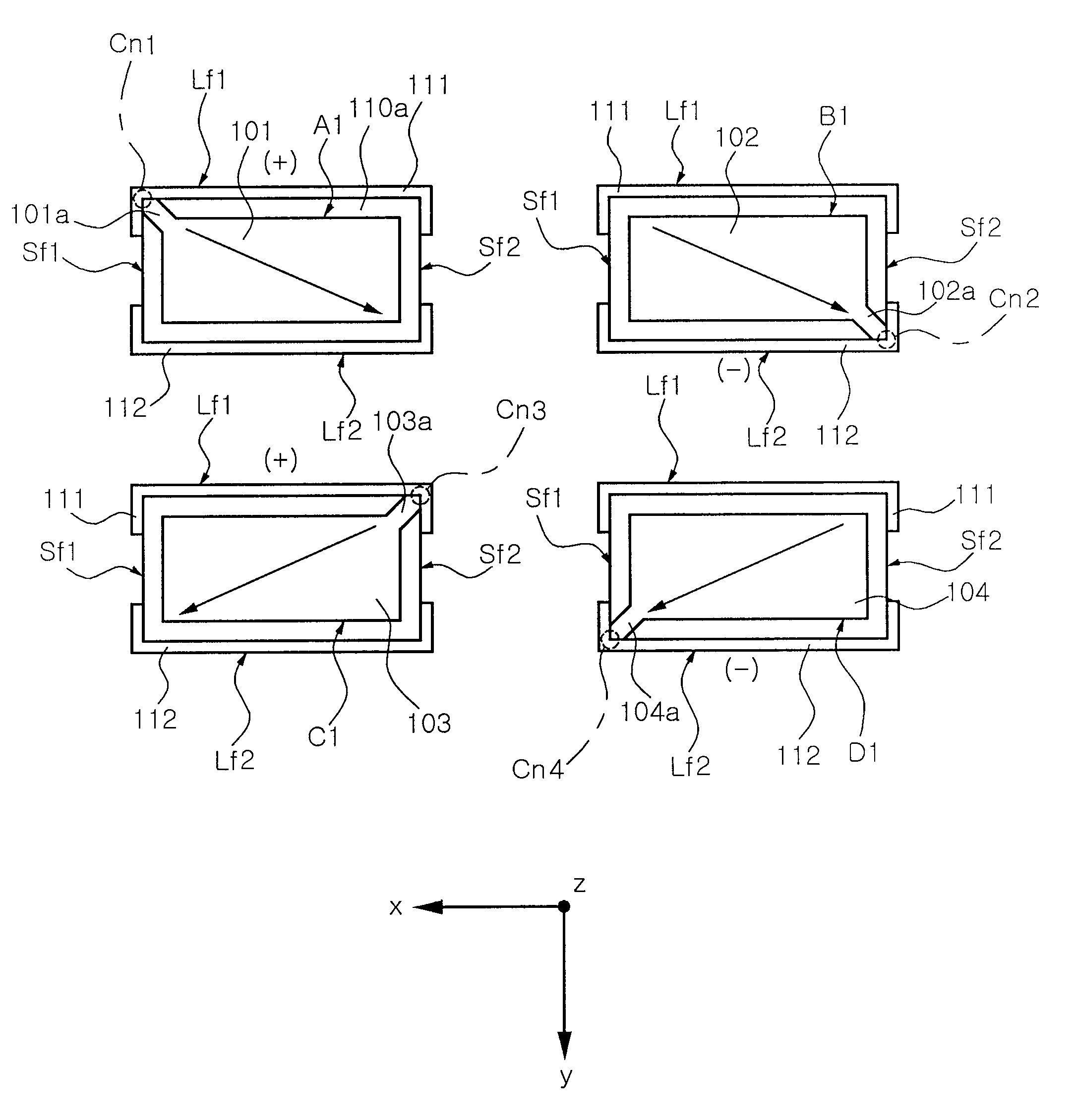
[0036]FIG. 2 is a perspective view of an exterior of a multilayer chip capacitor according to an exemplary embodiment of the present invention. FIG. 3 is a cross-sectional view of an internal electrode structure of the multilayer chip capacitor of FIG. 2. FIG. 4 is a sectional view taken along line X-X′ of FIG. 2.

[0037]Referring to FIG. 2, a multilayer chip capacitor 100 includes a capacitor body 110 having a rectangular parallelepiped shape with a top surface Tf, a bottom surfac...


PUM


Abstract

A multilayer chip capacitor includes a capacitor body including first and second longer side surfaces facing each other and first and second shorter side surfaces facing each other, first and second external electrodes respectively disposed at the first and second longer side surfaces, one or more first internal electrode pairs each including first and second internal electrodes, and one or more second internal electrode pairs each including third and fourth internal electrodes. The first to fourth internal electrodes each have one lead and are sequentially disposed in a stacked direction. The first to fourth internal electrodes have first to fourth leads respectively extending to first to fourth corners or portions adjacent thereto, and alternately connected with the first and second external electrodes. The first internal electrode pair and the second internal electrode pair cause a current to diagonally flow in opposite directions with respect to a long side direction.

Description

CROSS-REFERENCE TO RELATED APPLICATIONS[0001]This application claims the priority of Korean Patent Application No. 2008-15732 filed on Feb. 21, 2008, in the Korean Intellectual Property Office, the disclosure of which is incorporated herein by reference.BACKGROUND OF THE INVENTION[0002]1. Field of the Invention[0003]The present invention relates to a multilayer chip capacitor that is suitable to be used as a decoupling capacitor in a power distribution network of a micro process unit (MPU), and more particularly, to a 2-terminal low-inductance chip capacitor that can achieve high equivalent series resistance (ESR) while minimizing an increase in equivalent series inductance (ESL).[0004]2. Description of the Related Art[0005]An operating frequency for a high-speed micro processor unit (MPU) is continuously increasing, leading to an increase in current consumption, and an operating voltage for an MPU chip is being lowered. Thus, it becomes more difficult to suppress noise of a DC supp...

Claims


Application Information

Patent Timeline
Patent Type & Authority Patents(United States)
IPC IPC(8): H01G4/005H01G4/06H01G4/228
CPCH01G4/005H01G4/30
Inventor LEE, BYOUNG HWAWI, SUNG KWONCHUNG, HAE SUKPARK, DONG SEOKPARK, SANG SOOPARK, MIN CHEOL
Owner SAMSUNG ELECTRO MECHANICS CO LTD
Why Eureka
Try Eureka