System and method for minimizing DC offset in outputs of audio power amplifiers

a technology of audio power amplifier and direct current, which is applied in the field of audio power amplifier, can solve the problems of low efficiency, low efficiency, and insufficient relative high power input, and achieve the effects of minimizing or eliminating dc offset at power-on, avoiding undesirable noise, and high volum

Active Publication Date: 2008-05-27
SONOS
View PDF1 Cites 27 Cited by
  • Summary
  • Abstract
  • Description
  • Claims
  • Application Information

AI Technical Summary

Benefits of technology

[0005]The invention provides a new and improved system and method for minimizing or eliminating a direct current (“DC”) voltage offset in the outputs of audio power amplifiers.
[0007]Since the amplified output signal has a minimal or zero DC offset when the amplifier system is initially powered on, the amplifier system avoids generation of undesirable noises when it is initially powered-on. Since noises generated when an amplifier system is initially powered on can be relatively high volume, and thus can damage to components, such as speakers, to which it is attached, minimizing or eliminating DC offset at power-on can also reduce or eliminate the likelihood of such damage.

Problems solved by technology

Amplifiers in these classes generally make use of bipolar junction output transistors, which have fairly high power dissipation and relatively low efficiency.
The relatively low efficiency generally means that relatively high power input is necessary from the power supply to enable the amplifiers to provide desired volume levels.
In addition, the relatively high power dissipation generally means that relatively large and heavy heat sinks to dissipate the heat that is generated by the output transistors.
One problem that can arise in connection with class-D power amplifiers is that it is desirable to operate them at a zero-DC offset voltage level, that is, if the input signal to the power amplifier has a zero-DC voltage level with respect to ground, the output of the amplifier will also have a zero-DC offset voltage level, and if the input signal has a non-zero-DC waveform, the output waveform will also have a non-zero-DC waveform, but it will have zero-DC time average voltage level.
In any case, since the circuits make use of weighted time averages, they will not be effective when the power amplifier is initially powered on.
As a result, when the amplifier is initially powered on, it may have a non-zero-DC output signal, which can result in a pop or thump being generated by the speaker to which the amplifier is connected.
The pop or thump can be quite annoying, and can, in addition, damage components, such as speakers, to which the amplifier is attached, particularly if the amplifier has a relatively high gain.

Method used


Image

  • System and method for minimizing DC offset in outputs of audio power amplifiers
  • System and method for minimizing DC offset in outputs of audio power amplifiers
  • System and method for minimizing DC offset in outputs of audio power amplifiers

Examples


Embodiment Construction

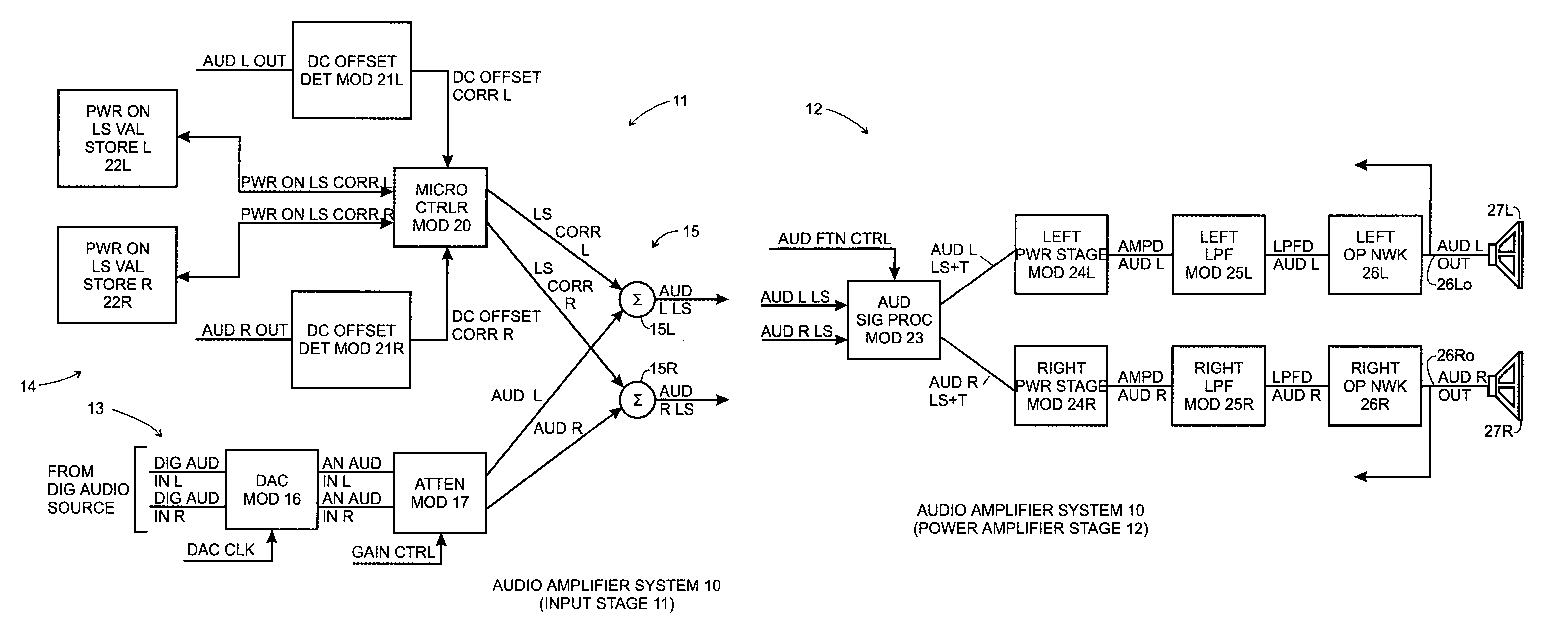
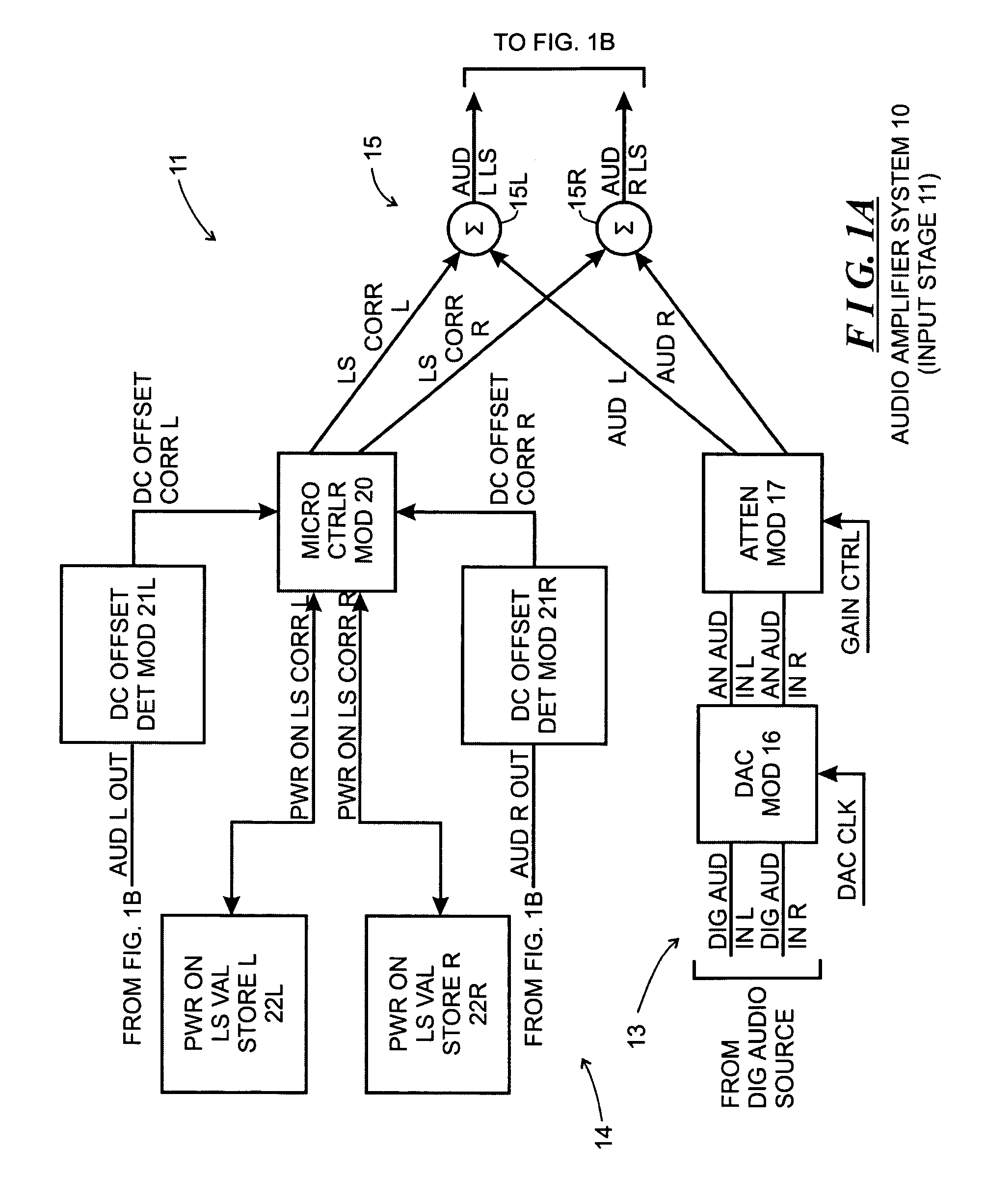
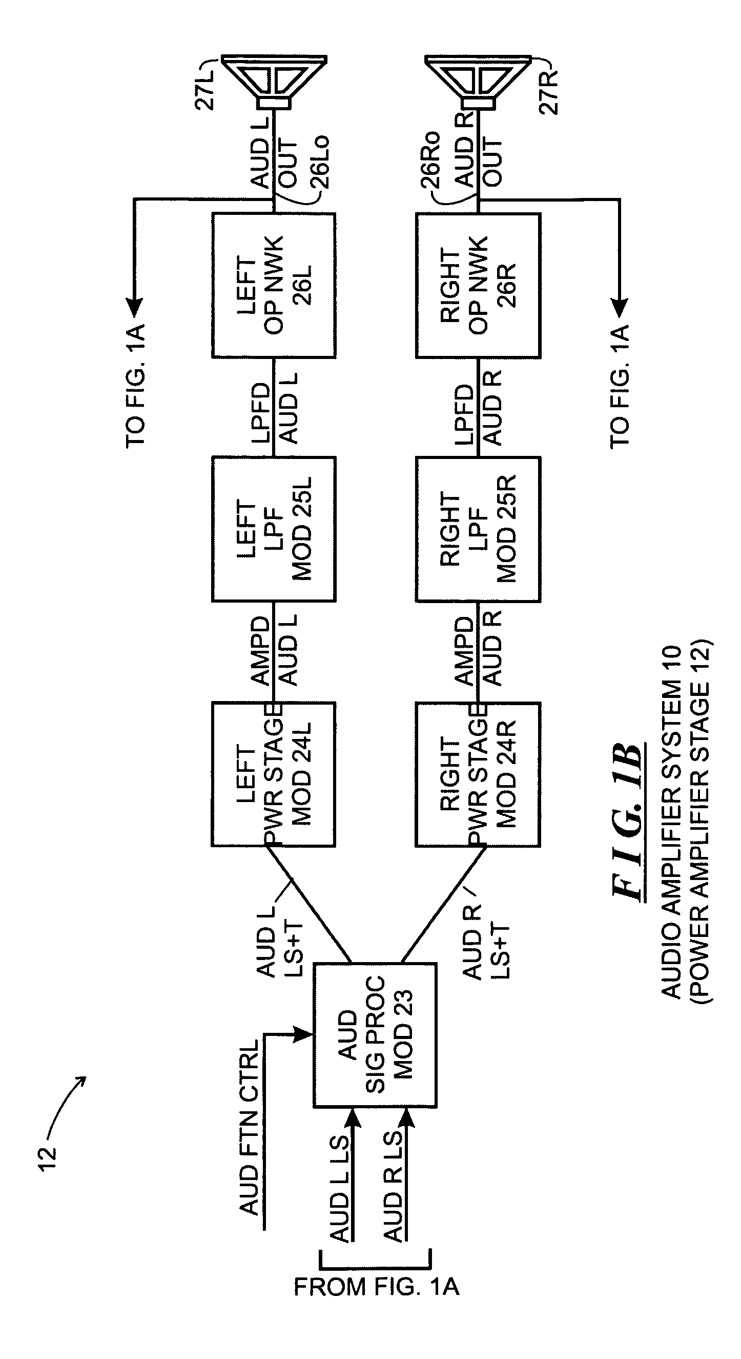
[0013]FIG. 1, comprising FIGS. 1A and 1B, depicts a functional block diagram of an audio amplifier system 10 constructed in accordance with the invention. The audio amplifier system 10 includes two general stages, including an input stage 11 (which is depicted in FIG. 1A) and a power amplifier stage 12 (which is depicted on FIG. 1B). Generally, the input stage 11 receives audio input signals, converts them as necessary from digital to analog form, attenuates the analog signals to facilitate gain control, and shifts the voltage level of the attenuated analog signals in a manner described below. In the audio amplifier system 10, the audio input signals are in digital form, and so the input stage 11 will include components to convert the digital audio input signals to analog form. The power amplifier stage 12 receives the level shifted analog signals, amplifies them and provides the amplified signals to output devices, such as speakers that can facilitate generation of sound waves for ...


PUM


Abstract

An amplifier system receives an input signal and generating therefrom an amplified output signal. The amplifier system is recited as comprising an input stage and an amplifier stage. The input stage is configured to receive the input signal and provide a level-shifted signal that has an average signal level that is shifted in regards a level shift value. The amplifier stage is configured to receive the level-shifted input signal from the input stage and generate therefrom the amplified output signal. The level shift value being selected to minimize a DC offset in the amplified output signal at least when the amplifier system is initially powered on. Since the amplified output signal has a minimal or zero DC offset, the amplifier system avoids generation of undesirable noises when it is initially powered on.

Description

FIELD OF THE INVENTION[0001]The invention relates generally to the field of audio power amplifiers, and more particularly to the field of systems and methods for minimizing a direct current (“DC”) offset in the output of class-D audio power amplifiers.BACKGROUND OF THE INVENTION[0002]A number of types of audio power amplifier designs have been developed, which have been grouped into various classes. Amplifiers in several classes, namely, class-A, class-B, class-AB and class-C, are referred to as linear power amplifiers, since the output signals generated by the amplifiers bear a generally linear relation to the input signal. Amplifiers in these classes generally make use of bipolar junction output transistors, which have fairly high power dissipation and relatively low efficiency. The relatively low efficiency generally means that relatively high power input is necessary from the power supply to enable the amplifiers to provide desired volume levels. In addition, the relatively high...

Claims


Application Information

Patent Timeline
Patent Type & Authority Patents(United States)
IPC IPC(8): H03F1/02
CPCH03F1/305H03F3/2171H03F3/2173H03F3/68H03F2200/03H03F2200/351H03F2200/375
Inventor BATES, L. DEXTER
Owner SONOS
Why Eureka
Try Eureka