Apparatuses for image forming capable of effectively conveying developer therefrom and a method of effectively forming a reinforcing member adhering to the apparatuses

a technology of image forming and apparatus, applied in the field of developer containers, can solve the problems of developer suction failure, self-size limitation of image forming apparatus,

Active Publication Date: 2008-06-17
RICOH KK
View PDF38 Cites 32 Cited by
  • Summary
  • Abstract
  • Description
  • Claims
  • Application Information

AI Technical Summary

Benefits of technology

[0017]Accordingly, one object of the present invention is to eliminate the above-described drawbacks.
[0018]Another object of the present invention is to provide a novel developer container capable of effectively conveying developer therefrom.
[0019]Another object of the present invention is to provide a novel method of effectively forming a reinforcing member attached to the novel developer container.
[0021]In one embodiment, a novel developer container includes a cap and a developer case. The cap is configured to control a flow of developer and includes a hole configured to be detachably engaged with a nozzle connected to an image forming apparatus. The developer case is configured to contain the developer and includes an outlet configured to be connected to the hole. The developer case allows the developer to flow through the outlet in a direction different from the flow of developer through the hole.
[0055]Further, in one embodiment, a novel image forming apparatus includes a developing unit and a developer container having a cap and a developer case. The developing unit is configured to develop a toner image. The cap of the developer container is configured to control a flow of developer and includes a hole configured to be detachably engaged with a nozzle connected to the image forming apparatus. The developer case of the developer container is configured to contain the developer and comprises an outlet configured to be connected to the hole. The developer case allows the developer to flow through the outlet in a direction different from the flow of developer through the hole.

Problems solved by technology

Therefore, the above-described developer container creates size limitations for itself and the image forming apparatus.
However, the above-described techniques may still cause developer suction failure.

Method used


Image

  • Apparatuses for image forming capable of effectively conveying developer therefrom and a method of effectively forming a reinforcing member adhering to the apparatuses
  • Apparatuses for image forming capable of effectively conveying developer therefrom and a method of effectively forming a reinforcing member adhering to the apparatuses
  • Apparatuses for image forming capable of effectively conveying developer therefrom and a method of effectively forming a reinforcing member adhering to the apparatuses

Examples


second embodiment

[0253]As shown in FIGS. 21 and 22, the developer container 320 of the second embodiment mainly includes the bottle 321, the cap 330, and a filter 329.

[0254]The bottle 321 includes a resin material such as polyethylene, polycarbonate, and / or nylon, and is blown-molded to have an average thickness of the resin material from approximately 1 mm to approximately 2 mm.

first embodiment

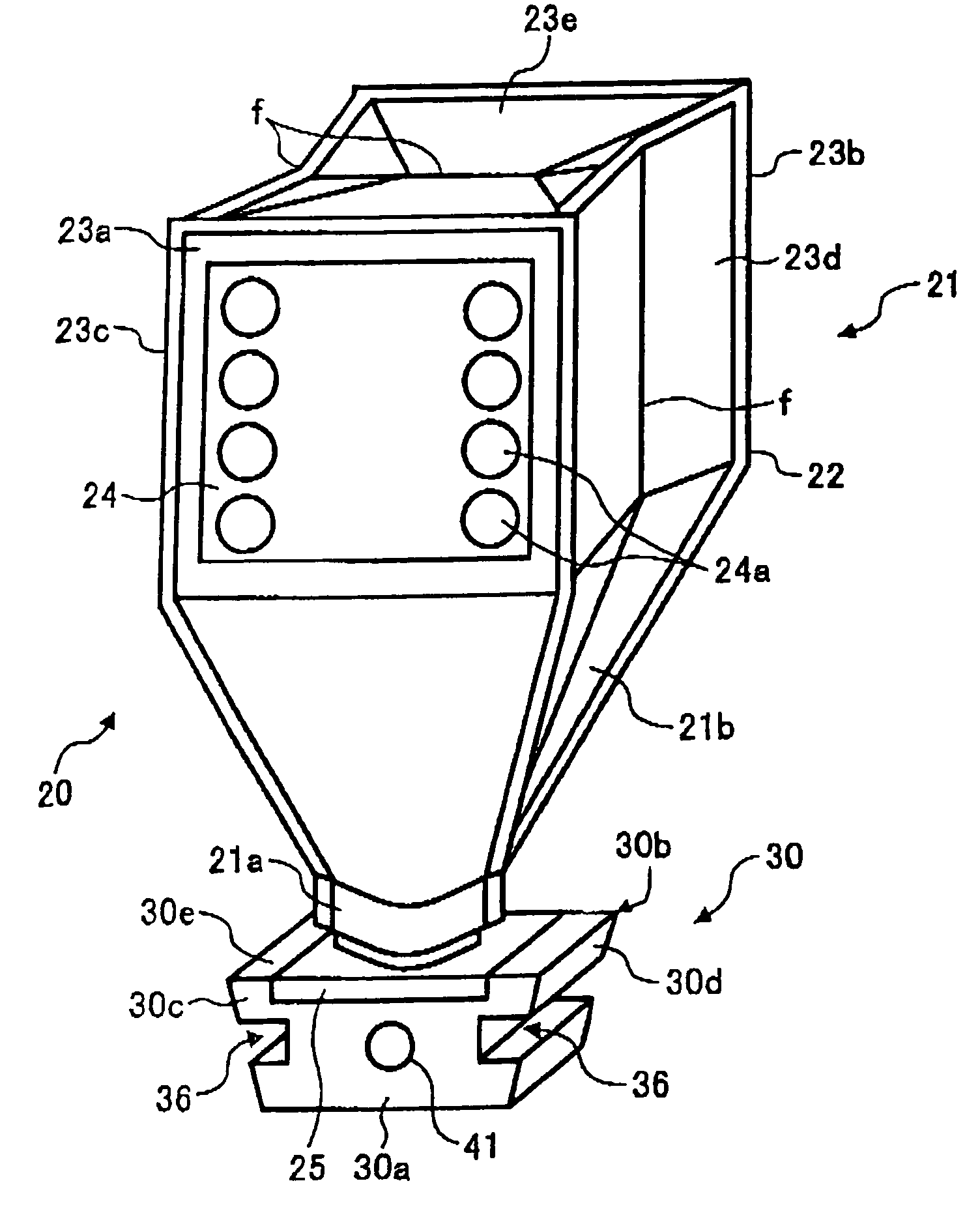
[0255]The bottle 321 includes, like the developer case 21 of the first embodiment, an opening 321a for discharging developer contained in the bottle 321. The opening 321a has an engaging member 326 and a developer outlet 327. The engaging member 326 engages with a guide member 347 of the cap 330. The developer outlet 327 communicates with a tapered inlet bore 333a of the cap 330.

[0256]The engaging member 326 and the developer outlet 327 are integrally mounted on the opening 321a. A nozzle-receiving hole 327 of the bottle 321 is received the funnel 333 of the cap 330.

[0257]The cap 330 includes a funnel 333, a tapered inlet bore 333a, grooves 336, a nozzle-receiving hole 341, the guide member 347, and a sponge seal 380. The cap 330 is basically similar to the cap 30, except for the sponge seal 380.

[0258]The sponge seal 380 is a sealing member including foamed polyurethane.

[0259]While the cap 30 has the O-ring 43 around the circumference of the funnel 33, the cap 330 has the sponge sea...


PUM


Abstract

A developer container includes a cap controlling a flow of developer with a hole, the cap detachably engaged with a nozzle connecting to an image forming apparatus, and a developer case containing the developer with an outlet be connected to the hole. The developer case allows the developer to flow through the outlet in a direction different from the flow of developer through the hole.

Description

CROSS-REFERENCE TO RELATED APPLICATIONS[0001]The present patent application claims priority under 35 U.S.C. § 119 to Japanese patent applications No. 2004-127537 filed on Apr. 23, 2004, and No. 2004-378907 filed on Dec. 28, 2004 in the Japanese Patent Office, the entire contents of each of which are hereby incorporated herein by reference.BACKGROUND OF THE INVENTION[0002]1. Field of the Invention[0003]The following disclosure relates to a developer container used for image forming, an image forming apparatus including the developer container and a method of forming a reinforcing member adhering to the developer container.[0004]2. Description of the Background Art[0005]The use of replaceable developer containers has widely been known to replenish developer consumed in a developing process of electrophotographic image forming. Such replaceable developer containers are replaced with a new or fully packed developer container whenever developer contained therein becomes short or is exhau...

Claims


Application Information

Patent Timeline
Patent Type & Authority Patents(United States)
IPC IPC(8): G03G15/08B65D83/06
CPCG03G15/0881G03G15/0877G03G15/0879G03G15/0874
Inventor KATSUYAMA, GOROKATOH, KEISUKEKITA, EMITAKAMI, NOBUO
Owner RICOH KK
Why Eureka
Try Eureka