Plasma processing apparatus and controlling method therefor

a technology of processing apparatus and plasma, which is applied in the direction of coating, coating, and plasma technique, can solve the problems of difficult adjustment of load matching devices, and achieve the effect of efficient energy conveying

Inactive Publication Date: 2006-03-02
TOKYO ELECTRON LTD
View PDF3 Cites 23 Cited by
  • Summary
  • Abstract
  • Description
  • Claims
  • Application Information

AI Technical Summary

Benefits of technology

[0009] The present invention attempts to solve the foregoing problem. An object of the present invention is to provide a plasma processing apparatus and control method for the plasma processing apparatus capable of efficiently conveying energy, which is generated by a microwave oscillator, to the load gas in a vacuum chamber.
[0011] According to the present invention, an impedance match is reliably attained and energy generated by the microwave oscillator can be efficiently transferred to the processing chamber.
[0013] The predetermined value may be variable. When the amount of adjustment is large, the value may be large. When the amount of adjustment is small, the multiple may be small. Thus, even when the load impedance varies due to a change in the state of the plasma, an impedance match can be reliably attained.

Problems solved by technology

However, the equivalent impedance in the plasma varies nonlinearly, depending on the density of plasma, and it is not easy to adjust the load matching device.

Method used


Image

  • Plasma processing apparatus and controlling method therefor
  • Plasma processing apparatus and controlling method therefor
  • Plasma processing apparatus and controlling method therefor

Examples


Embodiment Construction

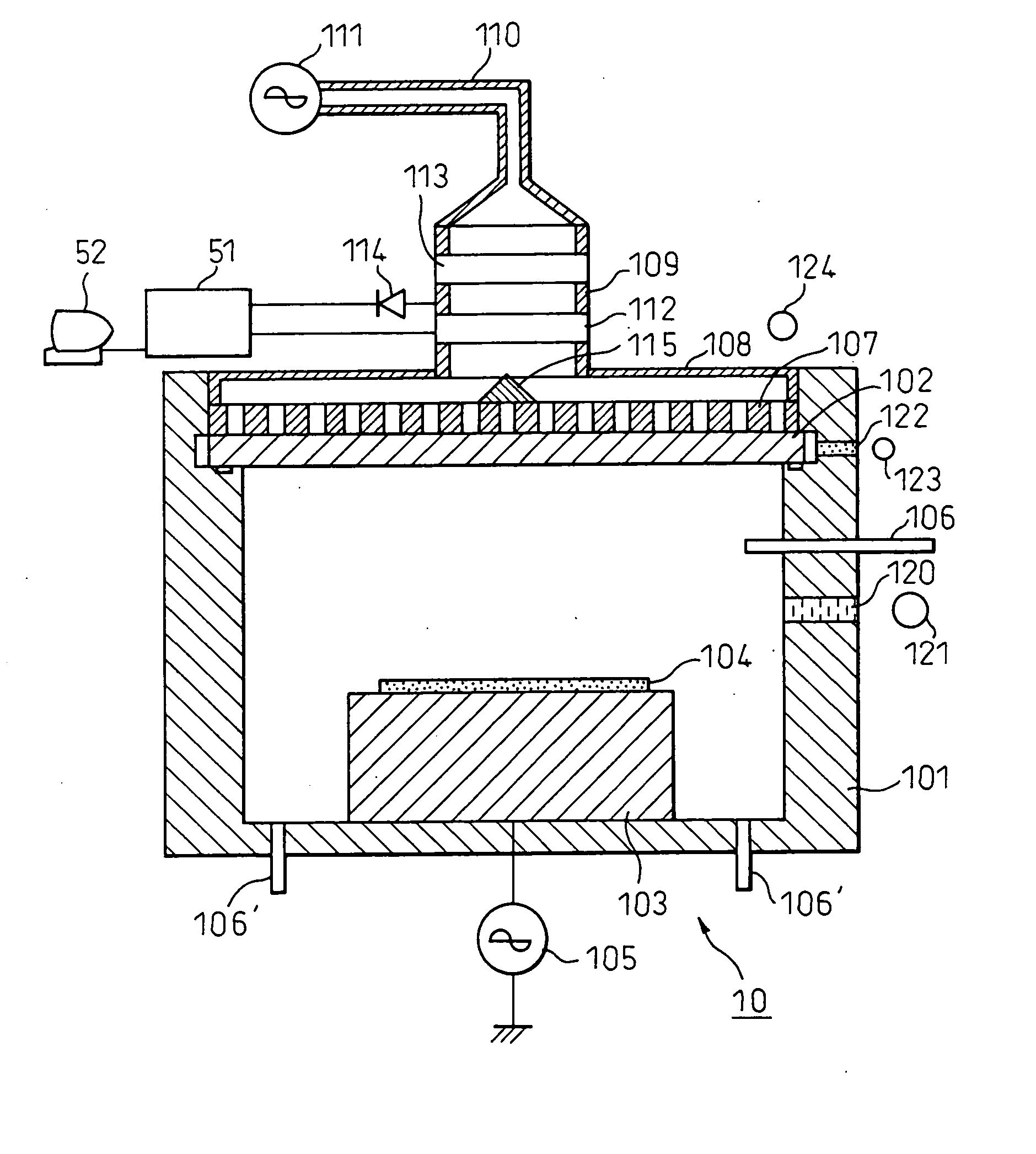
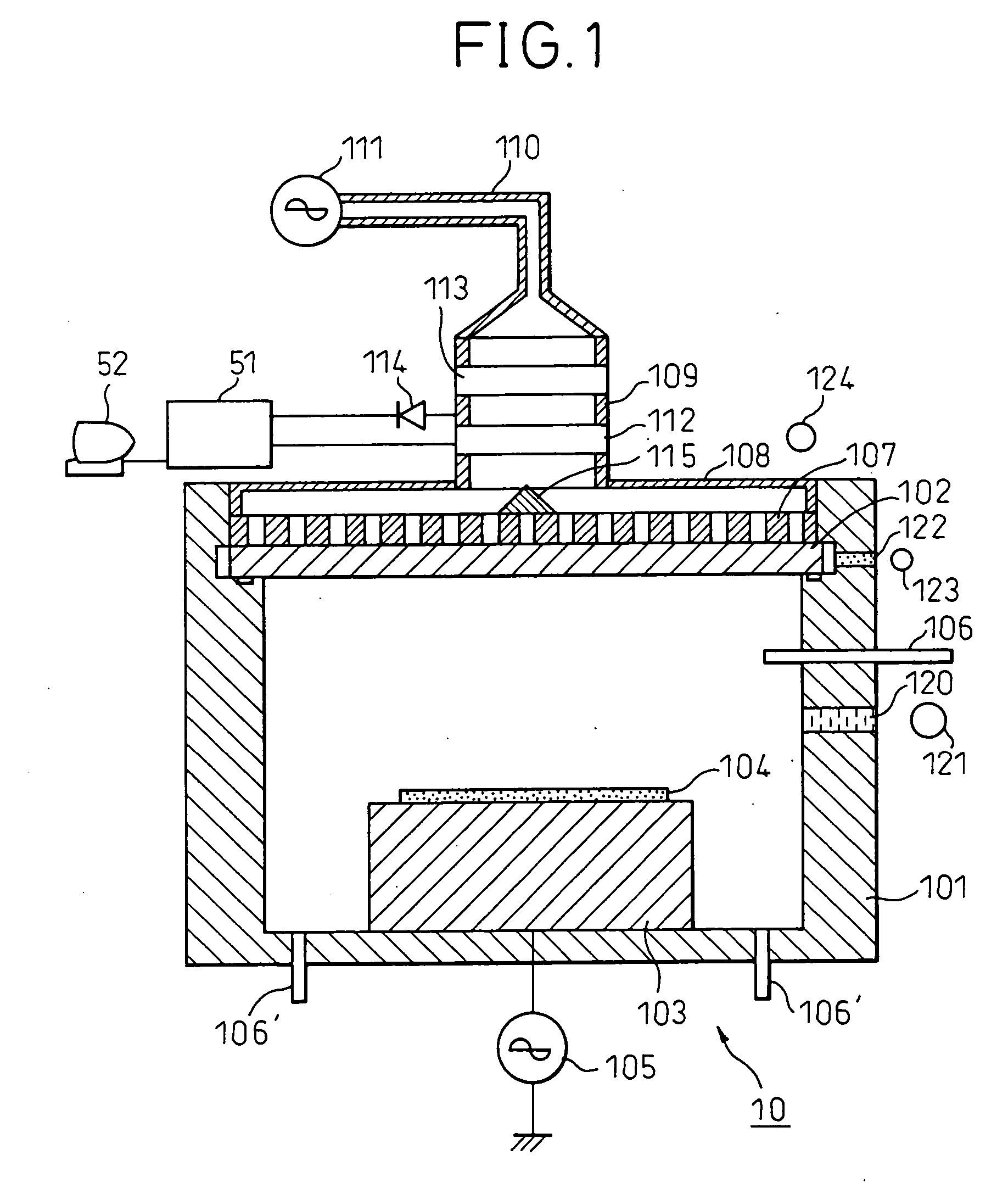
[0025]FIG. 1 is a sectional view of a plasma processing apparatus in which the present invention is implemented. A processing chamber 10 comprises a bottomed cylindrical container 101 and a quartz plate 102 serving as the lid of the bottomed cylindrical container 101.

[0026] A placement base 103 is put in the processing chamber 10, and a wafer 104 that is an object for plasma processing is loaded on the placement base 103. An electrostatic chuck may be installed in the placement base 103 in order to fix the wafer 104 to the placement base 103. A high-frequency bias power supply 105 is connected to the placement base 103.

[0027] A gas supply pipe 106 through which gas is supplied to the processing chamber 10 is embedded in the wall of the processing chamber 10, and exhaust pipes 106′ through which gas is discharged are embedded in the bottom thereof.

[0028] A flat-plate slot antenna 107 is mounted on the quartz plate 102, and covered with a disk-like radial waveguide box 108.

[0029] ...


PUM

PropertyMeasurementUnit
dielectric constantaaaaaaaaaa
impedanceaaaaaaaaaa
microwaves measurementaaaaaaaaaa

Abstract

A detector detects microwaves reflected from a processing chamber. Based on the reflected microwaves, a load impedance is calculated. An amount of adjustment required to match the load impedance with an impedance of a microwave oscillator is calculated. The calculated amount of adjustment multiplied by a predetermined value smaller than 1 is transmitted as an adjustment signal. A load matching device is repeatedly controlled based on the adjustment signal. Consequently, the load impedance gradually approaches the impedance of the oscillator. Eventually, an impedance match is attained.

Description

BACKGROUND OF THE INVENTION [0001] 1. Field of the Invention [0002] The present invention relates to a plasma processing apparatus for use in fabricating a semiconductor or a liquid crystal display panel, and a control method for the plasma processing apparatus. More particularly, the present invention is concerned with a microwave plasma processing apparatus capable of efficiently transmitting energy, which is generated by a microwave oscillator, to the load, a plasma, in a vacuum chamber. [0003] 2. Description of the Related Art [0004] For a semiconductor fabricating process, a plasma processing apparatus is used to perform physical vapor deposition (PVD), chemical vapor deposition (CVD), or the like so as to form a thin film on a wafer. [0005] The plasma processing apparatus is available in various types. In a widely adopted microwave plasma processing apparatus, microwaves are introduced from a microwave oscillator such as a magnetron into an antenna via a waveguide, and then ra...

Claims


Application Information

Patent Timeline
Patent Type & Authority Applications(United States)
IPC IPC(8): C23C16/00H01J37/32
CPCH01J37/32192H01J37/32311H05H1/461H05H2242/26
Inventor ISHII, NOBUOSHINOHARA, KIBATSU
Owner TOKYO ELECTRON LTD
Why Eureka
Try Eureka