Indwelling stent and living organ dilator

a living organ and stent technology, applied in the field of indwelling stents, can solve the problems of limited reduction in diameter by compression, and inability to compress the stent to a sufficiently small diameter, etc., to achieve small change in overall length, excellent shape retention, and reduced diameter

Active Publication Date: 2008-08-05
TERUMO KK
View PDF18 Cites 6 Cited by
  • Summary
  • Abstract
  • Description
  • Claims
  • Application Information

AI Technical Summary

Benefits of technology

[0012]It is an object of the present invention to provide a stent which is excellent in shape retention after expansion, is little changed in overall length upon expansion, and is capable of being reduced in diameter, and a living organ dilator using the stent.
[0014]In the indwelling stent, one of each adjacent pair of annular elements is located on the proximal end side in the axial direction of the stent, and the joints are substantially parallel to the stent axis, so that the length of the joints does not hamper the compression of the stent. Therefore, the stent can be compressed sufficiently to be small in diameter.
[0015]The annular elements are so arranged as to surround the stent axis and are joined to each other by the joints to form the annular unit, and the joints are substantially unchanged upon expansion of the stent. Therefore, the force for expansion will easily be exerted on the center of each annular unit, and each annular unit can be expanded evenly. The links also are substantially unchanged upon expansion of the stent, so that the overall length of the stent is little changed by the expansion of the stent.

Problems solved by technology

Therefore, even though the polygonal filamentous members (polygonal annular elements) can be compressed, it is difficult for the joints to be compressed, so that reduction in diameter by compression is limited, and it is impossible to compress the stent to a sufficiently small diameter.

Method used


Image

  • Indwelling stent and living organ dilator
  • Indwelling stent and living organ dilator
  • Indwelling stent and living organ dilator

Examples


example 1

[0095]A metallic pipe prepared from a stainless steel (SUS316L) pipe having a diameter of 3.0 mm and a material thickness of 0.2 mm by cutting to a length of 18.0 mm was used.

[0096]The stent was produced by blanking the stent portion from the metallic pipe. As the method for blanking the stent from the pipe, a variety of methods may be considered. Examples of the method include an etching method called photo-fabrication in which masking and a chemical agent is used, a discharge machining method using a die, and a mechanical cutting method. Here, a laser machining method which is the simplest and high in machining accuracy was used.

[0097]As a laser machining apparatus, a YAG laser (a product by NEC Corp.; product code: SL116E) was used. The metallic pipe was set on a motored jig equipped with a chuck mechanism so that offset of axis was not generated, and this assembly was set on an XY table capable of numerical control. The XY table and the motor were connected to a personal compute...

example 2

[0103]A stent was produced in the same manner as in Example 1, except that a development of a stent having the form as shown in FIG. 7 was inputted to the personal computer.

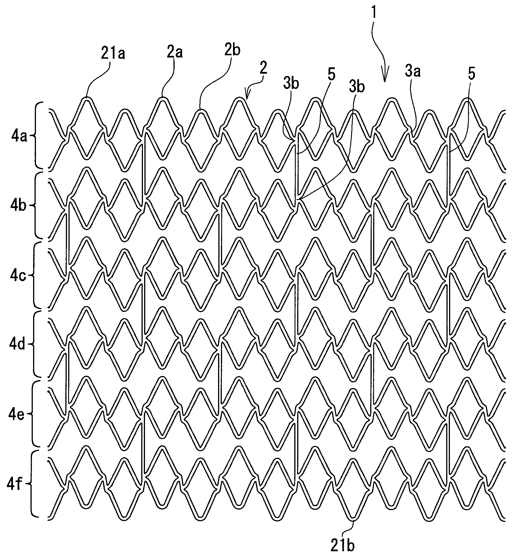
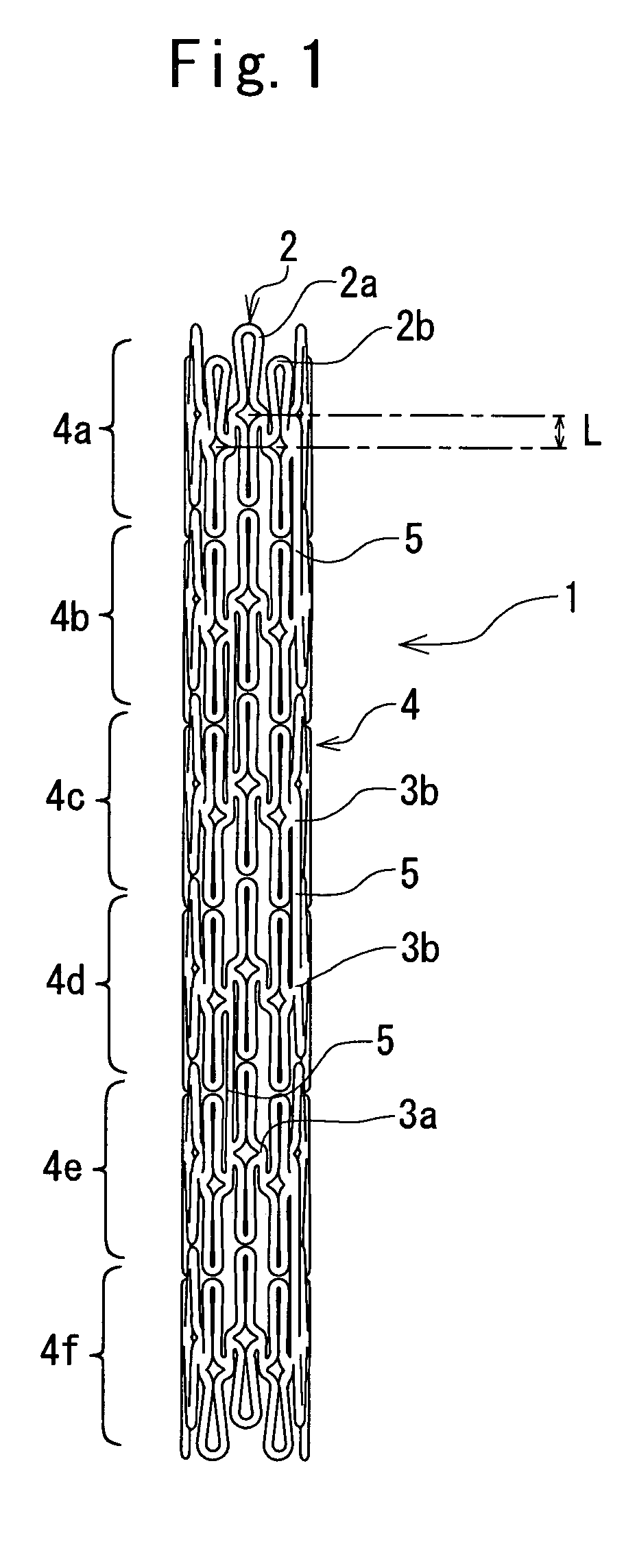
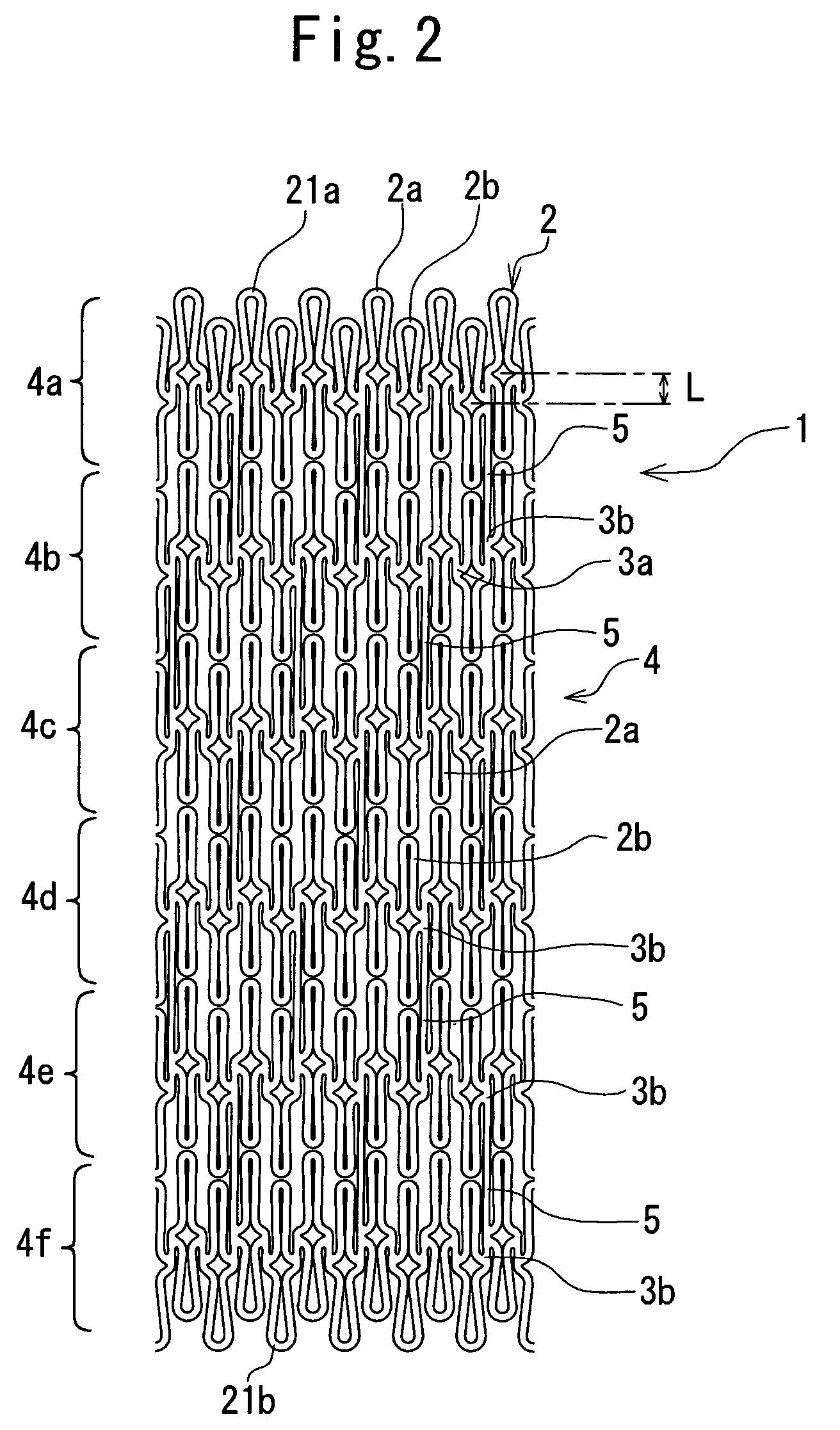
[0104]In the stent thus produced, each annular element was roughly rhombic in shape, with a major-axis length of 2.8 mm and a minor axis of 0.5 mm, and 12 annular elements were arranged at substantially regular angular intervals around the stent axis. The length by which the end portions of the adjacent annular elements in the annular unit were staggered from each other in the axial direction (in other words, the length of the axial component between the centers of the adjacent annular elements in the annular unit) was 0.5 mm, the length of the joints 3 extending slantly at a predetermined angle against the stent axis was 0.5 mm, and the length of one annular unit in the axial direction was 3.3 mm. The stent had an overall length of 18.0 mm and an outside diameter of 3.0 mm, comprised six annular units arranged i...

example 3

[0107]A stent was produced in the same manner as in Example 1, except that a development of a stent in the form as shown in FIG. 12 was inputted to the personal computer.

[0108]In the stent thus produced, each annular element was roughly rhombic in shape, with a major-axis length of 2.8 mm and a minor axis of 0.5 mm, and nine annular elements were arranged at substantially regular angular intervals around the stent axis. The length by which the end portions of the adjacent annular elements in the annular unit were staggered from each other in the axial direction (in other words, the length of the axial component of the interval between the centers of the adjacent annular elements in the annular unit) was 0.5 mm, the length of the joints 3 extending substantially in parallel to the stent axis was 0.5 mm, and the length of one annular unit in the axial direction was 3.3 mm. The stent had an overall length of 18.0 mm and an outside diameter of 3.0 mm, and the annular units were linked b...


PUM


Abstract

A stent includes annular units arranged in the axial direction of the stent, wherein each of the annular units includes a plurality of annular elements so arranged as to surround the stent axis, the adjacent annular elements being joined to each other through a joint, and the adjacent annular units are interconnected at their joints by at least one link. The annular elements in each annular unit are so arranged that one of the adjacent pair of annular elements is located on the proximal end side in the axial direction of the stent relative to the other of the adjacent pair of annular elements, end portions of each annular unit are projected zigzag, and the zigzag projected end portion of one annular unit is in the state of penetrating into the adjacent annular unit. The joints in each annular unit are substantially parallel to the stent axis.

Description

BACKGROUND OF THE INVENTION[0001]The present invention relates to an indwelling stent for use in improving constriction occurred in a living organism such as blood vessel, bile duct, trachea, esophagus, urethra, other organs, etc.[0002]A stent is a generally tubular tool having the function of maintaining a blood vessel or other incised lumen part in an opened state, and is used for improving stenosis of a blood vessel or the like.[0003]Stents are classified, by the function and indwelling method thereof, into self-expandable stents and balloon expandable stents. The balloon expandable stent does not have a self-expanding function, and is used in such a manner that the stent is inserted into a target site, then a balloon is located inside the stent, and the balloon is inflated to expand (plastically deform) the stent by the inflation force of the balloon, thereby bringing the stent into close contact with the inside surface of the target site and fixing the stent there. In this type...

Claims


Application Information

Patent Timeline
Patent Type & Authority Patents(United States)
IPC IPC(8): A61F2/06A61F2/915A61M29/00A61M29/02
CPCA61F2/91A61F2/915A61F2/958A61F2002/91508A61F2230/0054A61F2002/91533A61F2002/9155A61F2002/91558A61F2002/91566A61F2002/91516
Inventor KITAOKA, TAKASHIOKUSHI, NAOHISA
Owner TERUMO KK
Why Eureka
Try Eureka