Tinted lens assembly for recessed compact fluorescent lights

Inactive Publication Date: 2009-03-10
REYNOLDS ELAINE M
View PDF14 Cites 24 Cited by
  • Summary
  • Abstract
  • Description
  • Claims
  • Application Information

AI Technical Summary

Benefits of technology

[0021]An advantage of the present invention is economic use of compact fluorescent bulbs in recessed lighting fixtures without having to see the unsightliness of the bulb.
[0022]Another advantage of the present invention is that the lens reduces the normal white glare caused by fluorescent bulbs.
[0023]One more advantage of the present invention is that the lens is interchangeable with lenses of different tints, allowing for different effects for work lighting, holiday lighting, mood light

Problems solved by technology

Commonly used incandescent light bulbs utilize a substantial amount of electricity and create excessi

Method used


Image

  • Tinted lens assembly for recessed compact fluorescent lights
  • Tinted lens assembly for recessed compact fluorescent lights
  • Tinted lens assembly for recessed compact fluorescent lights

Examples


Example

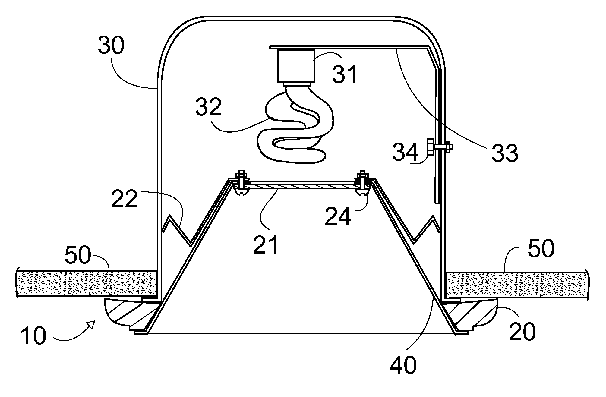
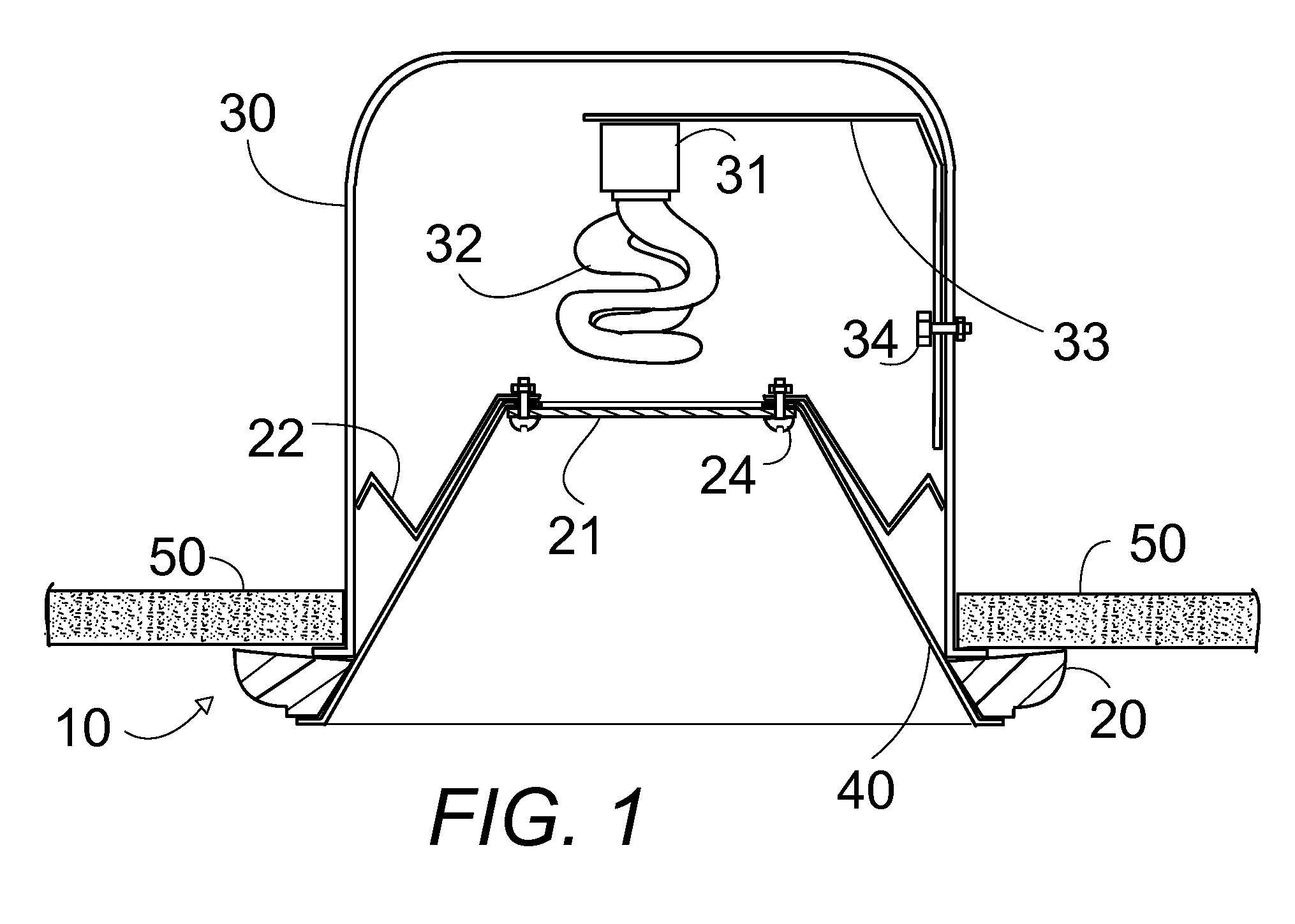
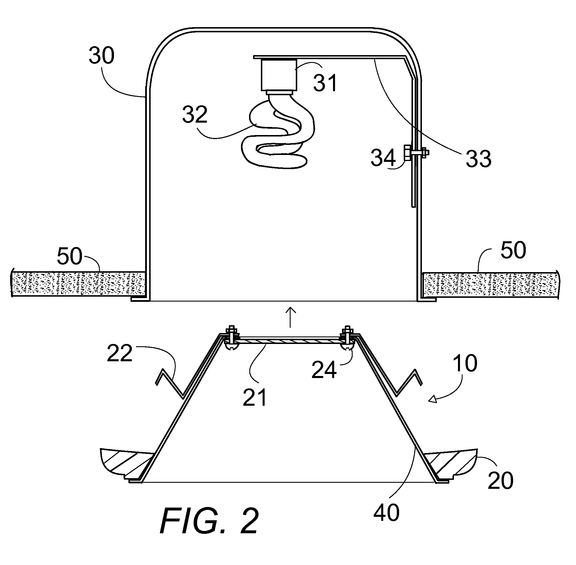
[0036]In FIGS. 1-7, a tinted lens and frame assembly 10 is installed in an existing recessed light unit 30 having a compact fluorescent bulb 32.

[0037]In FIGS. 1-4, the lens assembly 10 comprises a frame 20 structured to fit against a ceiling surface 50 surrounding a recessed lighting opening 30 in a ceiling. The recessed lighting opening 30 houses an existing recessed lighting can 30 with a light fixture socket 31 recessed within the can 30 to hold a compact fluorescent light bulb 32. In FIGS. 1-3, the frame 20 is seated on the preexisting light baffle 40 which extends into the recessed lighting opening. In FIG. 4, the light baffle 40 is attached with screws 26 to the frame 20. The light baffle 40 has a bottom opening that mates with the frame 20 and a top opening for admitting light therethrough. A tinted light transmitting lens 21 is attached at the top of the light baffle 40 to cover the top opening, the lens 21 being tinted to produce a desired light quality and the bottom surfa...


PUM


Abstract

A tinted glass lens is attached to an existing light baffle and a new frame to form a removable assembly. The assembly is installed in an existing ceiling recessed lighting fixture having a compact fluorescent bulb to cut glare and cover the bulb. The assembly removably attaches with tensioning spring hooks contacting an existing can. The tinted lens has a bottom reflective coating to match ceiling and can be interchanged with lenses of other tints to create desired lighting effects.

Description

CROSS-REFERENCE TO RELATED APPLICATIONS[0001]Not Applicable.STATEMENT REGARDING FEDERALLY SPONSORED RESEARCH OR DEVELOPMENT[0002]Not Applicable.THE NAMES OF THE PARTIES TO A JOINT RESEARCH OR DEVELOPMENT[0003]Not Applicable.BACKGROUND OF THE INVENTION[0004]1. Field of the Invention[0005]The present invention relates to lens holders or supports for light fixtures and particularly to a tinted lens and frame assembly which may be installed in an existing recessed light unit for use with a compact fluorescent bulb; the tinted lens and frame assembly comprising a glass lens which is tinted and coated with a camouflaging white reflective coating on an outer visible surface, and a frame whose color matches that of a white ceiling so that when the light is turned off all that is visible is the white frame, white baffle and white glass surface; the existing light baffle is attached to the new frame and the new tinted lens is attached to the existing baffle, tensioning spring hooks are attach...

Claims


Application Information

Patent Timeline
IPC IPC(8): F21V17/00
CPCF21S8/02F21S8/026F21V3/04F21V9/08F21V17/164F21V31/00F21V21/04F21Y2111/00Y02B20/386Y02B20/30
Inventor REYNOLDS, ELAINE M
Owner REYNOLDS ELAINE M
Why Eureka
Try Eureka