Speed bump devices

a technology of speed bumps and devices, applied in the direction of roads, traffic signals, road signs, etc., can solve the problems of undesirable speed bumps, appreciable bump effects, and unfavorable speed bumps on roads, and achieve the effect of more economic construction

Inactive Publication Date: 2009-03-24
GRIFFITHS DAVID GARDNER
View PDF7 Cites 17 Cited by
  • Summary
  • Abstract
  • Description
  • Claims
  • Application Information

AI Technical Summary

Benefits of technology

[0013]Forces exerted on a higher beam are readily transmissible to a beam on which it rests without necessarily passing through the connecting arms. The connecting arms, their pivot points, and any actuating mechanism for causing the displacement may therefore be more economically constructed as they do not need to be capable of bearing the maximum forces likely to be exerted between the beams, as compared to known speed bump devices where the means for bump extension is also the means for bump support.

Problems solved by technology

However, there are instances when a speed bump is undesirable.
For example, speed bumps are not desirable on roads where emergency vehicles frequently travel.
The speed bump device is provided with a lock which operates to lock the speed bump of the device in operative position when contacted by a vehicle wheel moving at a higher speed, thereby causing an appreciable bump effect.
The above-mentioned speed bump devices are unsuitable for use on roads and streets where heavy vehicles and vehicles carrying heavy loads travel.

Method used


Image

  • Speed bump devices
  • Speed bump devices
  • Speed bump devices

Examples


Embodiment Construction

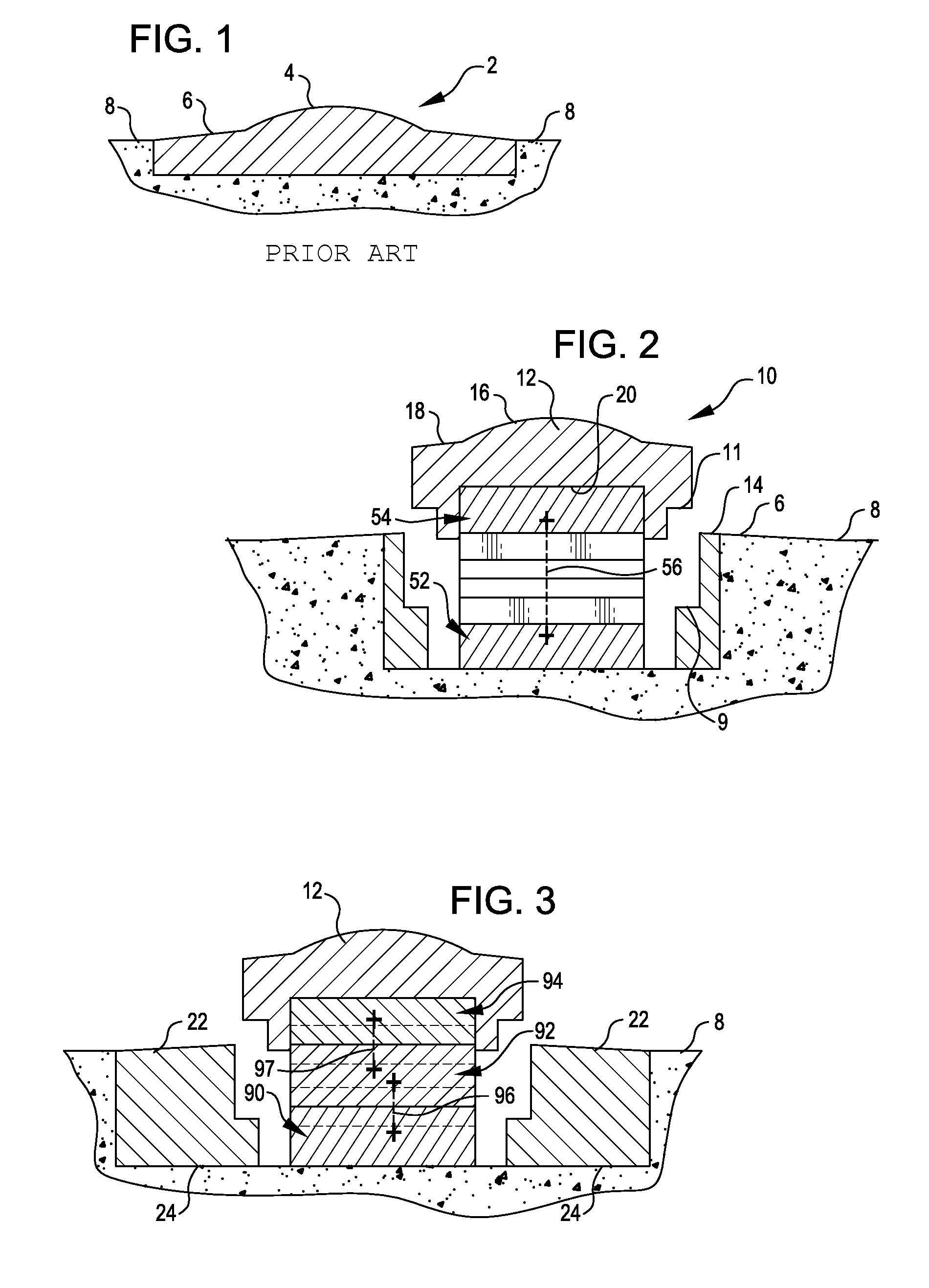
[0033]FIG. 1 shows a speed bump device 2 known in the art. Device 2 comprises a raised element 4 and lead up ramps 6, which forms part of road surface 8.

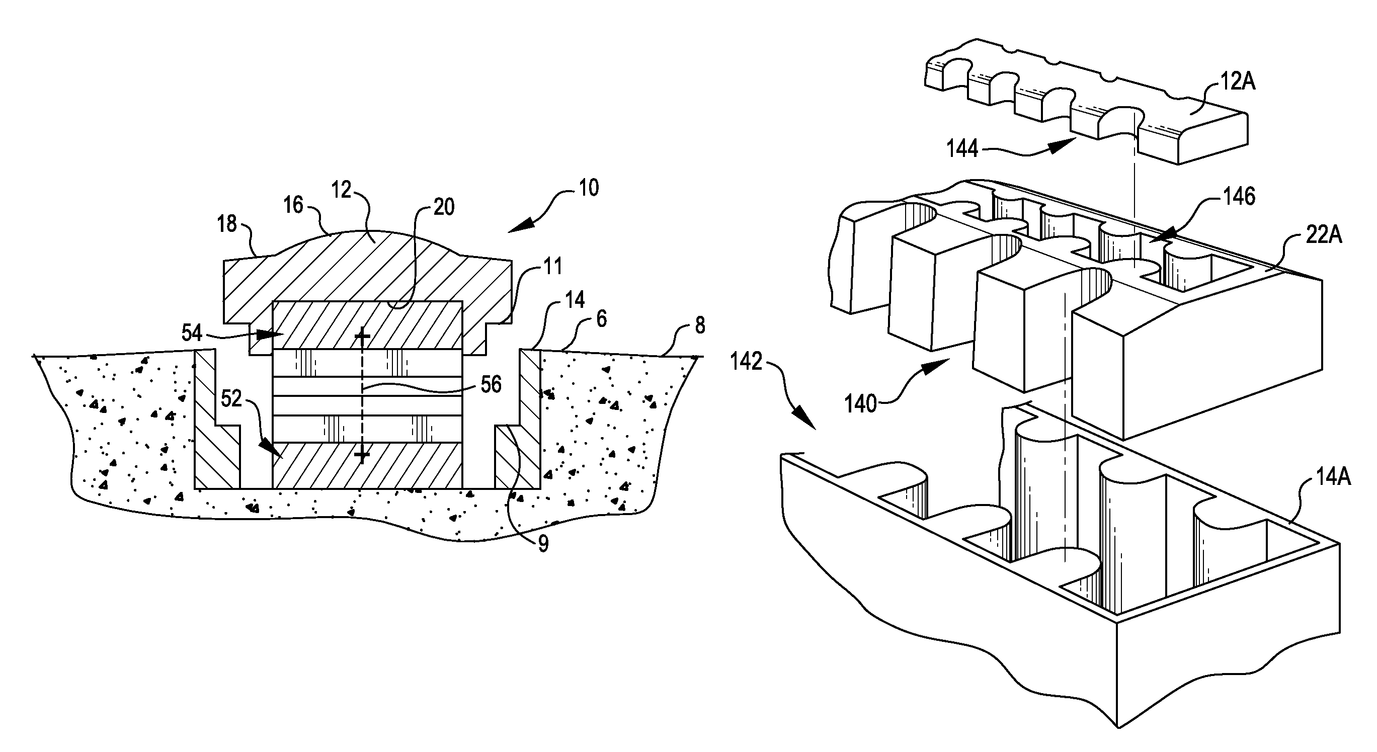
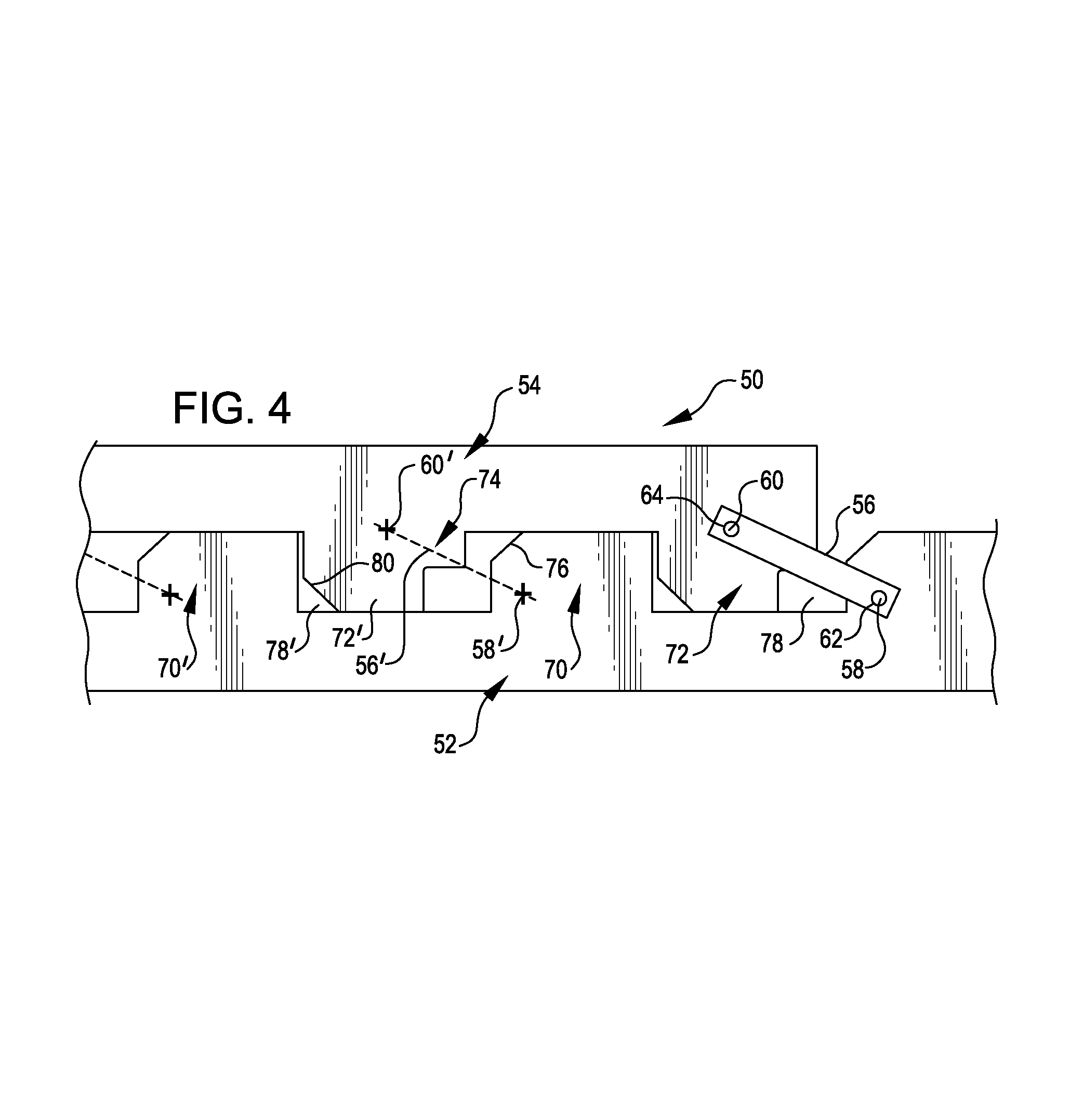
[0034]FIG. 2 shows an embodiment of the disclosed speed bump device 10. Speed bump device 10 comprises a moveable central road surface element 12 provided with a central raised portion 16 and shoulders 18. The road surface element 12 is positioned in guide means in the form of a frame 14 that is embedded in a road surface 8. Road surface 8 leads up to the frame 14 by way of ramps 6. The road surface element 12, extendable and retractable, is upwardly and downwardly movable within frame 14. The upward and downward movements are brought about by the action of an underlying parallelogram frame 50 as shown in FIG. 4, which will be further described below. An upper beam 54 of parallelogram frame 50 pushes against the underside 20 of the road surface element 12 when element 12 is being extended or raised, forming a bump.

[0035]Rotatable be...


PUM


Abstract

A speed bump device is provided. The speed bump device comprises a first parallelogram frame, wherein the frame comprises an upper nested beam and a lower nested beam, wherein the upper beam and the lower beam are connected by way of at least one pivotable connecting arm, wherein the lower beam comprises at least one depression and at least one raised section, and wherein the upper beam is displaceable, relative to the lower beam, by way of the at least one connecting arm, from a retracted position, through a maximally extended position, to a raised position. A road surface element may suitably overlie the upper beam.

Description

FIELD OF THE INVENTION[0001]This invention relates to speed bump devices. Particularly, this invention relates to retractable speed bump devices suitable for use and installation on roads, streets, and the like.BACKGROUND OF THE INVENTION[0002]It is known that speed bumps are generally raised elements installed on roads or streets designed to discourage and prevent vehicles from travelling at high speed by way of giving jolts to the vehicles travelling too quickly over the speed bumps. However, there are instances when a speed bump is undesirable. For example, speed bumps are not desirable on roads where emergency vehicles frequently travel.[0003]Several retractable speed bumps have been developed. U.S. Pat. No. 4,342,525 (Mastronuzzi, Jr.) discloses a retractable speed bump mounted in a street, road, or roadway for controlling the speed of vehicles, which includes a generally rectangularly-shaped encasement containing upper and lower, relatively movable, wedge-shaped members slidab...

Claims


Application Information

Patent Timeline
Patent Type & Authority Patents(United States)
IPC IPC(8): E01F11/00
CPCE01F9/047E01F9/529
Inventor GRIFFITHS, DAVID GARDNER
Owner GRIFFITHS DAVID GARDNER
Why Eureka
Try Eureka