Image correction apparatus

a technology of image correction and apparatus, which is applied in the field of image correction apparatus, can solve the problems of unresolved above problems, and generating glaze, so as to achieve high brightness and lightness, and prevent the effect of unnecessarily reducing brightness or lightness

Active Publication Date: 2009-05-26
ORMON CORP
View PDF20 Cites 28 Cited by
  • Summary
  • Abstract
  • Description
  • Claims
  • Application Information

AI Technical Summary

Benefits of technology

[0012]In the second mode of the invention, the degree of correction performed to each pixel is determined according to how much the color component of each pixel is close to the color component which is a dominant to the predetermined region. Therefore, for example, the color component which is a dominant to the predetermined region is designed to become the skin color of the subject, which allows the correction to be performed according to the skin color of the subject. In this case, the degree of correction can be set larger in the portion which is the skin color of the subject, and the degree of correction can be set so as to be suppressed to a small amount in the portion which is not the skin color of the subject. Accordingly, only the glaze generated in the skin of the subject can be removed or reduced, and the brightness generated in the domains except for the skin can be maintained.
[0031]In order to solve the above problems, in the correction device in the second mode, the third mode, or the fourth mode, the smoothing process is performed to the value indicating the degree of correction. Therefore, the correction in which only a certain domain is extremely corrected compared with the surroundings can be prevented, and the image correction can be realized more naturally.

Problems solved by technology

Conventionally, in the image in which the person is taken, there is a problem that the so-called “glaze” is generated.
Such the glaze gives discomfort impression to a person who sees the image.
The above problem cannot be solved even by the method of selecting the domain including the eyes of the subject person from the image.

Method used


Image

  • Image correction apparatus
  • Image correction apparatus
  • Image correction apparatus

Examples


operation example

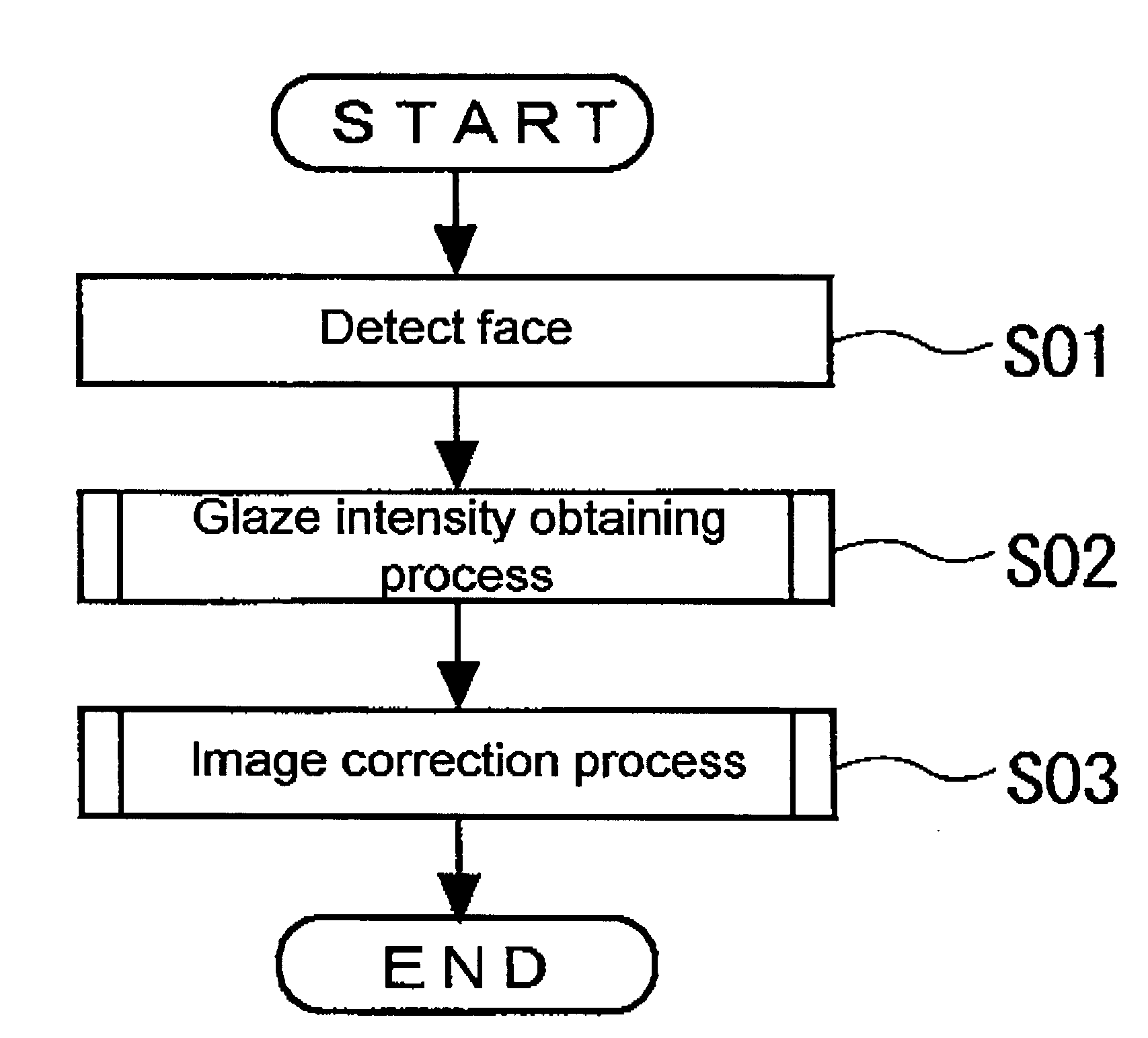
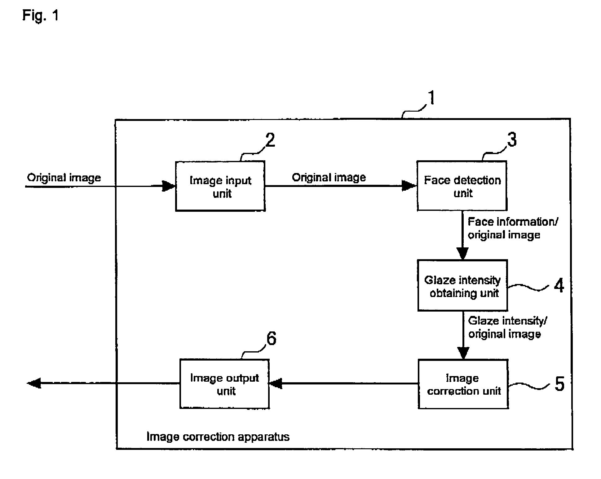
[0114]FIG. 10 shows a flowchart of an operation example of the image correction apparatus 1. Referring to FIG. 10, an operation example of the image correction apparatus 1 will be described. First the face detection unit 3 detects the person face of the subject from the inputted image (S01), and the face information is obtained. Then, the glaze intensity obtaining unit 4 obtains the glaze intensity of each pixel by performing the glaze intensity obtaining process (S02).

[0115]FIG. 11 shows an operation example of the image correction apparatus 1 in the glaze intensity obtaining process. In FIG. 11, the process of obtaining the glaze intensity by the method in which the first obtaining process and the third obtaining process are combined is shown as an example. Referring to FIG. 11, the glaze intensity obtaining process will be described.

[0116]The glaze intensity obtaining unit 4 computes the high-brightness intensity for each pixel in the original image (S04). Then, the glaze intensi...


PUM

PropertyMeasurementUnit
brightnessaaaaaaaaaa
glossaaaaaaaaaa
skin coloraaaaaaaaaa

Abstract

An object of the invention is to provide an apparatus which performs correction only to a high-brightness portion generated in a particular region, in which a decrease in brightness is necessary, and glaze is removed or reduced. A correction process in which the brightness or the lightness is decreased is simply performed to a pixel in which the brightness or the lightness is high, but a predetermined region (for example, face, eyes, and mouth) of a subject is detected and a degree of correction of each pixel is determined based on the detection result (a position and a color of the predetermined region). Therefore, the region in which the decrease in brightness is not necessary is maintained at high brightness, and the image correction is performed only to the region in which the decrease in brightness is necessary (for example, the region in which the glaze of a skin is generated).

Description

BACKGROUND OF THE INVENTION[0001]1. Field of the Invention[0002]The present invention relates to an effective technology which is applied to image correction to a taken image, particularly to the taken image in which a subject is a person.[0003]2. Description of the Background Art[0004]Conventionally, in the image in which the person is taken, there is a problem that the so-called “glaze” is generated. The glaze means that a part of skin is taken in white because light of a stroboscope and the like emitted in taking a photograph is reflected from surface of the skin of the subject person. Therefore, a region in which the glaze is generated (hereinafter referred to as “glaze region”) is taken in higher brightness when compared with surrounding skin. Such the glaze gives discomfort impression to a person who sees the image. Therefore, the technology which removes or reduces the glaze is required in the image in which the glaze has been generated.[0005]Conventionally a correction metho...

Claims


Application Information

Patent Timeline
Patent Type & Authority Patents(United States)
IPC IPC(8): G06K9/00G03F3/08G06K9/40G06T5/00G06T1/00H04N1/387H04N1/40H04N1/46H04N1/60H04N1/62
CPCG06T5/008G06T5/40H04N1/6086H04N1/62H04N1/628G06T5/002G06T2207/10024G06T2207/20012G06T2207/20148G06T2207/30201G06T7/136
Inventor TABATA, NAOHIROYOSHIDA, YOKO
Owner ORMON CORP
Why Eureka
Try Eureka