Electronic endoscope system having processor device, and method for processing endoscopic image

Active Publication Date: 2012-04-26
FUJIFILM CORP
View PDF5 Cites 15 Cited by
  • Summary
  • Abstract
  • Description
  • Claims
  • Application Information

AI Technical Summary

Benefits of technology

[0019]According to the present invention, when the binning process is applied to the special image such as the autofluorescence image, the binning number is determined in accordance with

Problems solved by technology

However, neither the US Patent Application Publication No. 2009/0036743 nor the Japanese Patent Laid-Open Publication No. 2001-170009 di

Method used


Image

  • Electronic endoscope system having processor device, and method for processing endoscopic image
  • Electronic endoscope system having processor device, and method for processing endoscopic image
  • Electronic endoscope system having processor device, and method for processing endoscopic image

Examples


Example

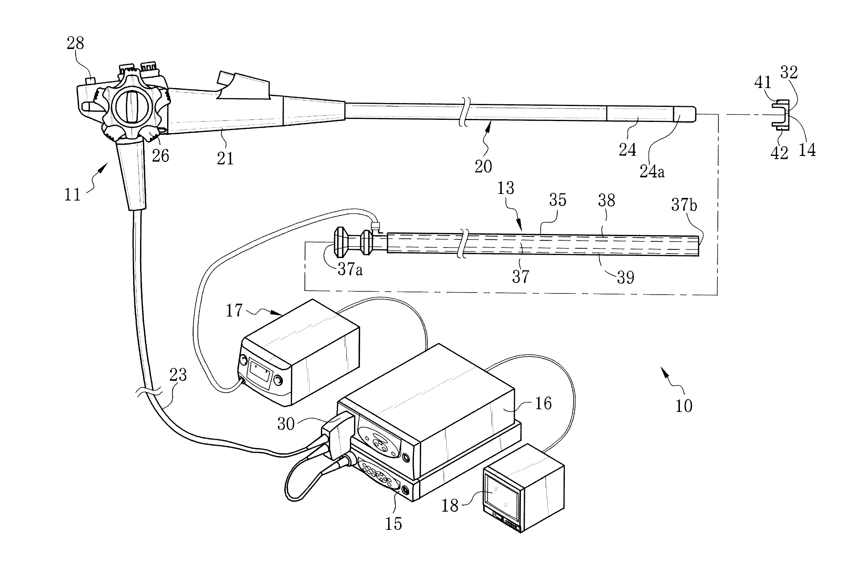
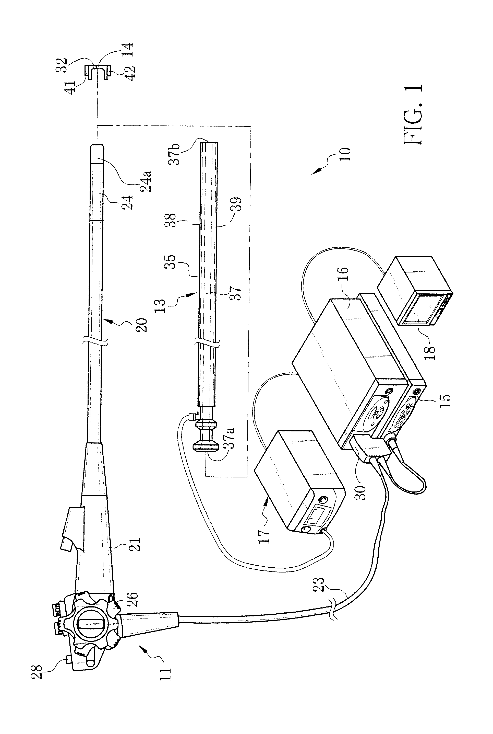
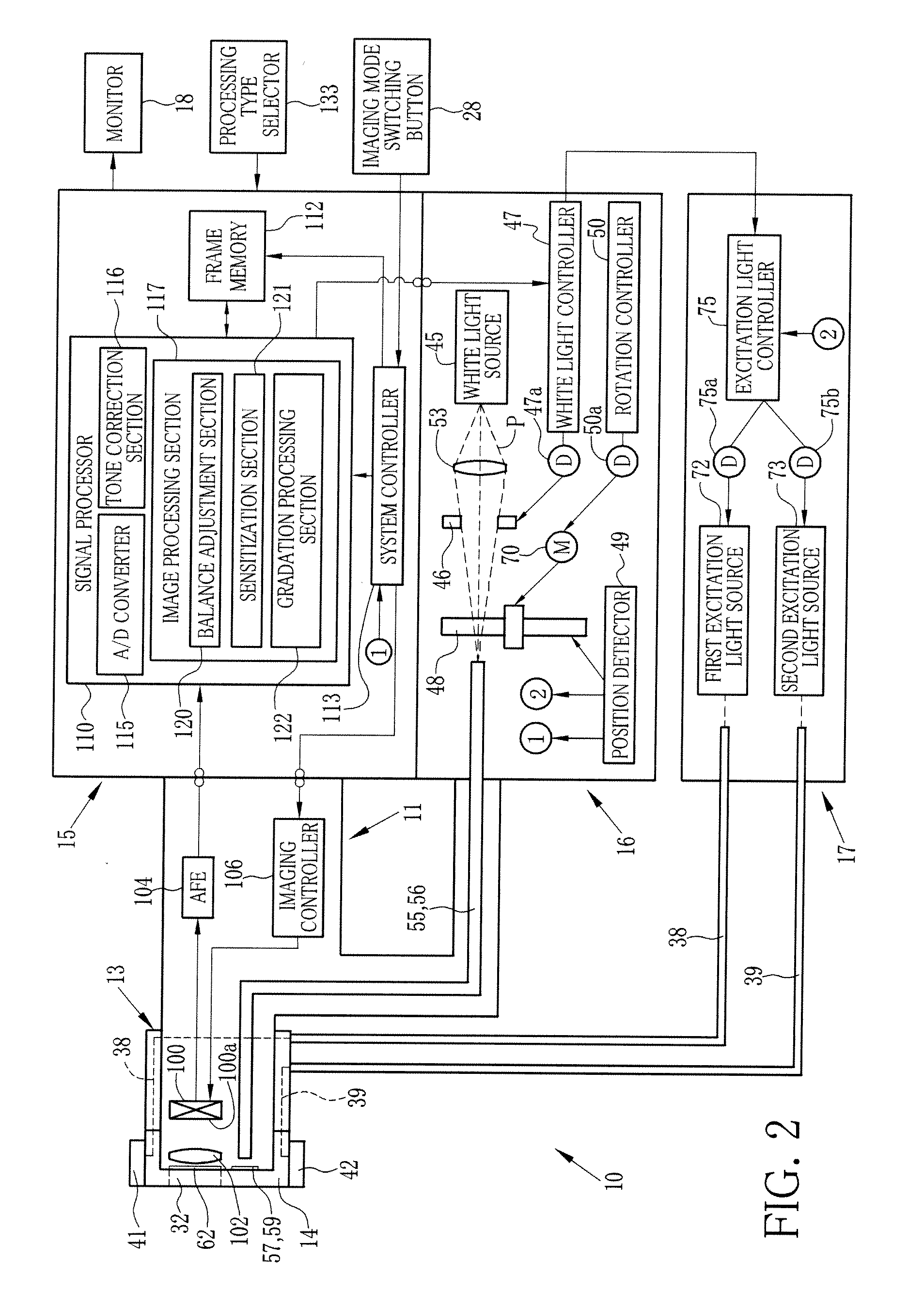
[0048]An electronic endoscope system 10 of a first embodiment, as shown in FIG. 1, has an autofluorescence imaging (AFI) function for imaging autofluorescence emitted from living body tissue inside a patient's body cavity. The electronic endoscope system 10 is provided with an electronic endoscope 11, an over-tube 13, a hood 14, a processor device 15, a normal light source device 16, a special light source device 17, and a monitor 18. The electronic endoscope 11 captures an image inside the patient's body cavity with an image sensor such as a CCD. Into the over-tube 13, an insert section 20 of the electronic endoscope 11 is inserted. The hood 14 is attached to a distal end portion 24a of the insert section 20. The processor device 15 produces an endoscopic image of the internal body part based on a signal obtained by the CCD. The normal light source device 16 supplies white light (normal light) to irradiate the internal body part therewith. The special light source device 17 supplie...

Example

Second Embodiment

[0108]In a second embodiment of the present invention, an electronic endoscope system 200, as shown in FIG. 16, carries out narrow band imaging (NBI) in which narrow band light is applied to the internal body part to display a superficial blood vessel with enhancement. The structure of the electronic endoscope system 200 according to the second embodiment is partly different from that of the electronic endoscope system 10 of the first embodiment.

[0109]The electronic endoscope system 200 is provided with an NBI-specific light source device 201, instead of the normal light source device 16 and the special light source device 17 of the first embodiment. In the electronic endoscope system 200, in contrast to the first embodiment, the hood 14 having the excitation light cut filter 32 and the first and second light projection units 41 and 42 is not attached to the distal end portion 24a of the electronic endoscope 11, and the over-tube 13 containing the optical fibers 38 ...

Example

Third Embodiment

[0118]An electronic endoscope system 230 according to a third embodiment, as shown in FIG. 18, has the function of obtaining blood vessel information related to the depth of a blood vessel and blood oxygen saturation inside the body cavity. The structure of the electronic endoscope system 230 according to the third embodiment is partly different from that of the electronic endoscope system 10 of the first embodiment.

[0119]The electronic endoscope system 230 is provided with a light source device 231 for blood vessel information obtainment, instead of the normal light source device 16 and the special light source device 17 of the first embodiment. In the electronic endoscope system 230, in contrast to the first embodiment, the hood 14 having the excitation light cut filter 32 and the first and second light projection units 41 and 42 is not attached to the distal end portion 24a of the electronic endoscope 11, and the over-tube 13 containing the optical fibers 38 and 3...


PUM


Abstract

White light and excitation light are applied to an internal body part. An electronic endoscope captures a normal image of the internal body part irradiated with the white light, and a special image of autofluorescence emitted from living body tissue of the internal body part irradiated with the excitation light. An object distance detector detects an object distance between a CCD and an inspection area of the internal body part based on the normal image. A binning processing section applies a binning process to the special image. There are two types of binning processes, i.e. an intensity adjustment process and a resolution adjustment process. In the intensity adjustment process, the binning number is increased with increase in the object distance. In the resolution adjustment process, the binning number is decreased with increase in the object distance. Which process to perform is determined by operation on a processing type selector.

Description

BACKGROUND OF THE INVENTION[0001]1. Field of the Invention[0002]The present invention relates to an electronic endoscope system having a special imaging function such as autofluorescence imaging (AFI) and narrow band imaging (NBI).[0003]2. Description Related to the Prior Art[0004]In a medical field, diagnosis and treatment using an electronic endoscope system are widely carried out in recent years. In the electronic endoscope system, while white light (normal light), which ranges from a blue wavelength band to a red wavelength band, is applied to the inside of a patient's body cavity, an image sensor such as a CCD captures an image of the light reflected from an internal body part. The captured image is displayed on a monitor. The electronic endoscope system can image the inside of the human body cavity in real time, and facilitates the accurate diagnosis and the effective treatment.[0005]The image (normal image) captured under the normal light shows an overview of the internal bod...

Claims


Application Information

Patent Timeline
IPC IPC(8): A61B5/1459A61B1/04
CPCA61B1/00009A61B1/043A61B1/0638A61B1/0653A61B1/063A61B1/0646G02B23/2469A61B1/000094A61B1/0655
Inventor YAMAGUCHI, HIROSHIIIDA, TAKAYUKIYASUDA, HIROAKIMUROOKA, TAKASHI
Owner FUJIFILM CORP
Why Eureka
Try Eureka