
Stereoscopic Panoramic imaging system

Inactive Publication Date: 2008-12-04
IMAGE MASTERS
View PDF32 Cites 253 Cited by
  • Summary
  • Abstract
  • Description
  • Claims
  • Application Information

AI Technical Summary

Benefits of technology

[0040]It is therefore an object of the present invention to provide an improved imaging system for capturing stereoscopic panoramic images. Such a system will have numerous advantages.
[0041]One advantage is that by using multiple imager pairs to capture stereoscopic images instead of a single imaging pair, this system captures stereo images in all directions at one time with no moving parts. This permits immersive stereo imaging at video rates.
[0042]Another advantage is the construction using a rigid mechanical frame, which allows the system to maintain high levels of calibration from image set to image set and over extended periods of time.

Problems solved by technology

Mass-produced consumer cameras of the early-to-mid-1900's were not practical for taking stereo photographs because re-positioning for the second view of a scene requires significant handling to yield satisfactory results.
Similar radial arrangements of multiple cameras can provide limited stereo image acquisition, but only in peripheral areas of lens coverage where adjacent images overlap.
However, imaging devices are intentionally not paired nor are they mounted exclusively at normal interocular separation distances.
Thus, there is not a demonstrated design intention to avoid hyperstereo effects for any panoramic stereo images they may capture.
This design further risks hyperstereo effects by not pairing imagers at normal interocular separation distances.
The problem with this design is both hyperstereo effects and visual interference by the mirrors in the viewing space of adjoining imagers.
Rogina uses epipolar techniques to synthesize the two stereoscopic views rather than using two directly-captured images, limiting real-time performance in stereoscopy.
One obvious drawback is the interference of the physical mirrors in the fields-of-view of adjoining imagers.
Further, the construction of the mosaics takes additional processing with the concomitant expenses of hardware and software, as well as time.
However, stereo coverage is not necessarily complete nor are imagers appropriately spaced to simulate normal eye-separation distances.
Both Pierce's and McCutchen's cameras share the limitation that the various images when viewed as pairs are of necessity at a variety of angles and elevations.
As such, they are therefore not practical for producing normal panoramas in stereoscopy.
All of the afore-mentioned imaging arts suffer from impractical production of stereo images across a wide panorama.
Further complex processing is needed in all cases to adjust for rectilinearity and interocular spacing effects to construct usable stereo images around the horizontal viewing plane.
Most multi-imager cameras also suffer in keeping imagers aligned with respect to each other.
A failure in calibration retention makes these prior arts impractical for use on a day-to-day basis.
As a single plate, Barman's approach works well for viewing in a single direction but does not address instantaneous panoramic capture.
The disadvantage of Barman is that the planar nature of the metal plate limits stereo viewing to one direction and to the extent of angular coverage of the lenses.
While providing a panoramic view, none of these inventions provides a stereoscopic view of the surroundings.
The obvious limitation is that objects can shift or move and lighting conditions can change during the time it takes to reset the position of the camera.
Another problem is that mechanical movements of a camera will result in different relative positions of images at a fine resolution.
Furthermore, video acquisition is not possible with this design.
This miniaturization effect varies with distance from the imager pair and makes the images unsuitable for normal stereoscopic viewing of 3D space.
Obviously, with a plurality of cameras, inward-looking systems may achieve stereo imaging, but convergent points-of-view do not provide for panoramic capture and are therefore not the subject of this inventive field.
A further limitation to this type of design is difficulty in maintaining calibration between cameras and loss of precision due to wear and variation in mechanical movements.
As such, they do not address flaws existing in the actual imaging subsystems themselves.
Imaging subsystem flaws exist in lenses and imagers and affect color, brightness, and pixel displacement.
None of these cameras produces stereo images or handles imager-pair-related differences.
Most are for specialized use and are delicate in design, requiring frequent recalibration to retain optimum stereo configurations.
Image transform engines have been designed that remap pixels of a camera's output but do not correct all distortions, color aberrations, and lens errors in a single process.
Nor are there any that transform images automatically prior to image transmission or storage.
Despite the varieties of stereoscopic or panoramic solutions available, there exists an unfulfilled need for a stereoscopic imaging system that can capture both still and video panoramic images at normal interocular separation distances with a variety of lens types.
In summary, there currently exists no imaging system that effectively captures stereoscopic panoramic or panospheric images and handles flaws and variations in the system on a dynamic and automated basis.

Method used


Image

  • Stereoscopic Panoramic imaging system
  • Stereoscopic Panoramic imaging system
  • Stereoscopic Panoramic imaging system

Examples


Embodiment Construction

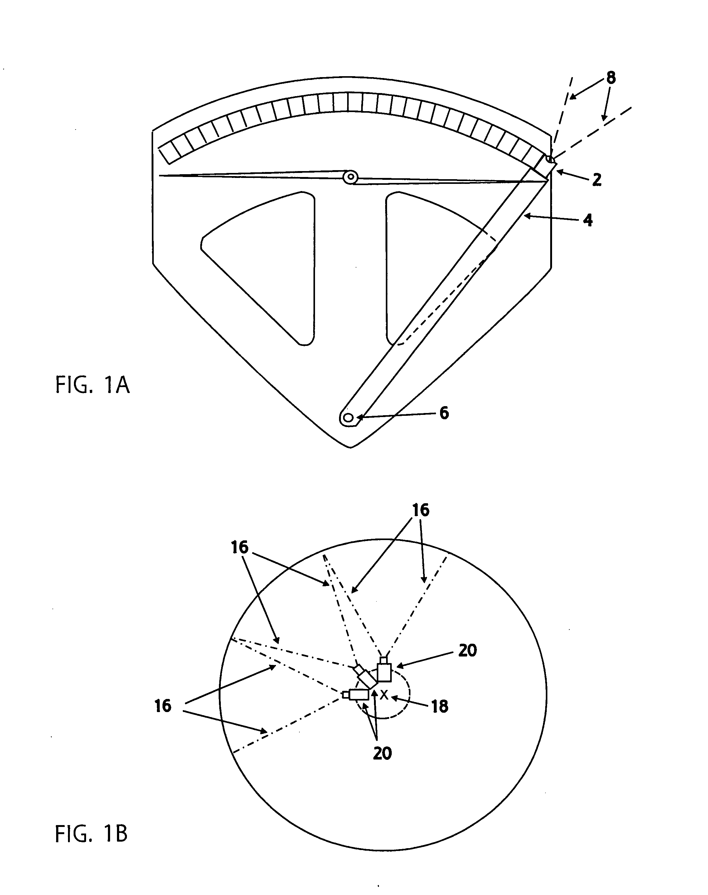
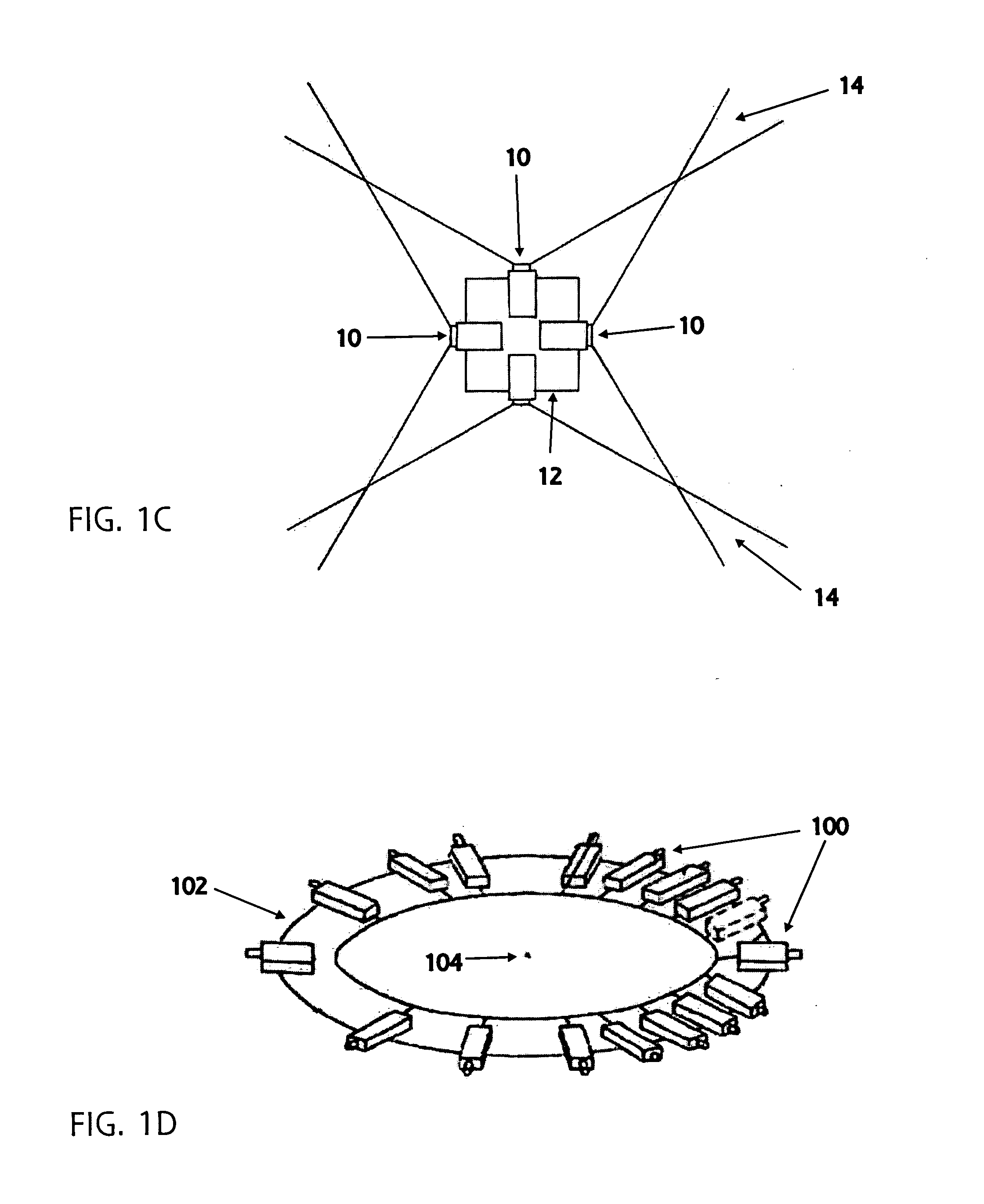
[0065]The present invention describes an improved and practical stereoscopic imaging system designed to fully capture panoramic or panospheric image pairs. These are collected as either still or video images generated by a plurality of coplanar imager pairs rigidly mounted around a central point. Hence, there are no moving parts in this imaging system. This simplified system produces overlapping stereo image pairs to cover a full 360° field of view without having to produce a mosaic. The system accepts a wide variety of lens arrangements and types, correcting for differences between observed and captured images. Such differences are due to the normal effects of wide angle imaging, as well as lens flaws.

[0066]The coplanar arrangement within imager pairs is essential for stereo viewing to reduce post-acquisition correction. An example of such a correction is the adjustment for mutual image sizes caused by having imaging subsystems at different distances from an object field. Furthermo...


PUM


Abstract

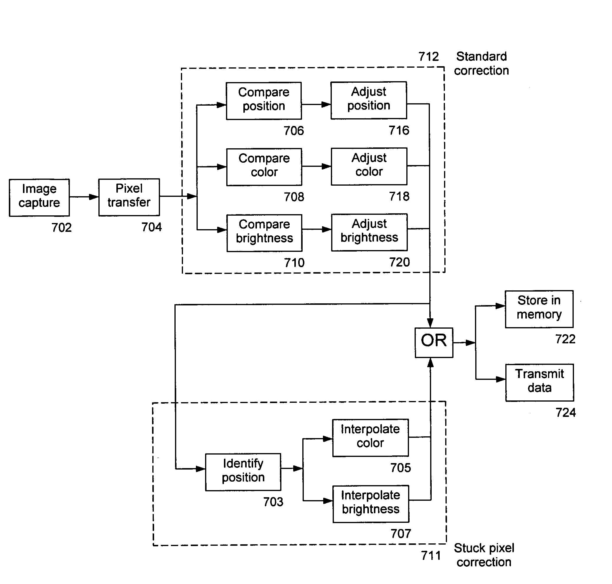
An imaging system for producing stereoscopic panoramic images using multiple coplanar pairs of image capture devices with overlapping fields of view held in a rigid structural frame for long term calibration maintenance. Pixels are dynamically adjusted within the imaging system for position, color, brightness, aspect ratio, lens imperfections, imaging chip variations and any other imaging system shortcomings that are identified during calibration processes. Correction of pixel information is implemented in various combinations of hardware and software. Corrected image data is then available for storage or display or for separate data processing actions such as object distance or volume calculations.

Description

CROSS-REFERENCE TO RELATED APPLICATIONS[0001]This non-provisional application for patent is related to U.S. provisional patent application 60 / 924,690 filed on May 29, 2007 and entitled “Stereoscopic panoramic imaging system.” The applicants for this non-provisional application remain the same as for the previously filed provisional application and include Robert G. Baker, Frank A. Baker, and James Connellan. The benefit under 35 USC section 119(e) of the United States provisional applications are hereby claimed, and the aforementioned application is hereby incorporated herein by reference.STATEMENT REGARDING FEDERALLY SPONSORED RESEARCH[0002]Not ApplicableREFERENCE TO SEQUENCE LISTING[0003]Not ApplicableBACKGROUND OF THE INVENTION[0004]1. Field of the Invention[0005]This invention relates to the field of immersive imaging, in which images of complete visual environments are captured collectively, describing a stereoscopic panoramic imaging system with high structural integrity and r...

Claims


Application Information

Patent Timeline
IPC IPC(8): G06K9/36G06V10/147
CPCG06K9/209H04N5/2251H04N5/23238H04N5/247H04N13/0025H04N13/0242H04N13/0246G03B35/08G03B37/04H04N13/243H04N13/246H04N13/133G06V10/147H04N23/60H04N23/50H04N23/698H04N23/90
Inventor BAKER, ROBERT G.BAKER, FRANK A.CONNELLAN, JAMES A.
Owner IMAGE MASTERS
Learn More