Device for charging at least one battery

a technology for charging devices and batteries, applied in charging stations, electrical apparatus construction details, transportation and packaging, etc., can solve the problems of high charging capacity, and achieve the effect of reducing the maximum necessary cooling capacity and improving the cooling capacity

Active Publication Date: 2019-01-17
DR ING H C F PORSCHE AG
View PDF23 Cites 12 Cited by
  • Summary
  • Abstract
  • Description
  • Claims
  • Application Information

AI Technical Summary

Benefits of technology

[0011]The spatial separation of the electronics module and the charging pillar permits a modular design, and the charging pillar can be made slender. In addition, the charging pillar can be embodied in a low-noise fashion, since the cooling of the power electronics does not have to occur directly in the charging pillar.
[0040]According to one preferred embodiment, the cooling module is fluidically connected to at least two power electronics units, connected in parallel, to form a coolant circuit, wherein controllable through-flow control means are provided in order to be able to influence in relation to one another the cooling capacity for the at least two power electronics units which are connected in parallel. As a result, the maximum necessary cooling capacity can be set lower, since all the charging points are not continuously occupied or charged with the full charging capacity. The cooling capacity which is present can be used better with the through-flow control means.

Problems solved by technology

There is a general aim to charge electric vehicles quickly, and this requires high charging capacities which are very demanding in terms of the charging device.

Method used


Image

  • Device for charging at least one battery
  • Device for charging at least one battery
  • Device for charging at least one battery

Examples


Embodiment Construction

[0058]The device or charging station can be provided at a car park with a charging facility, but it is also possible to configure an electric charging station which is located, for example, on a freeway like a freeway gas station.

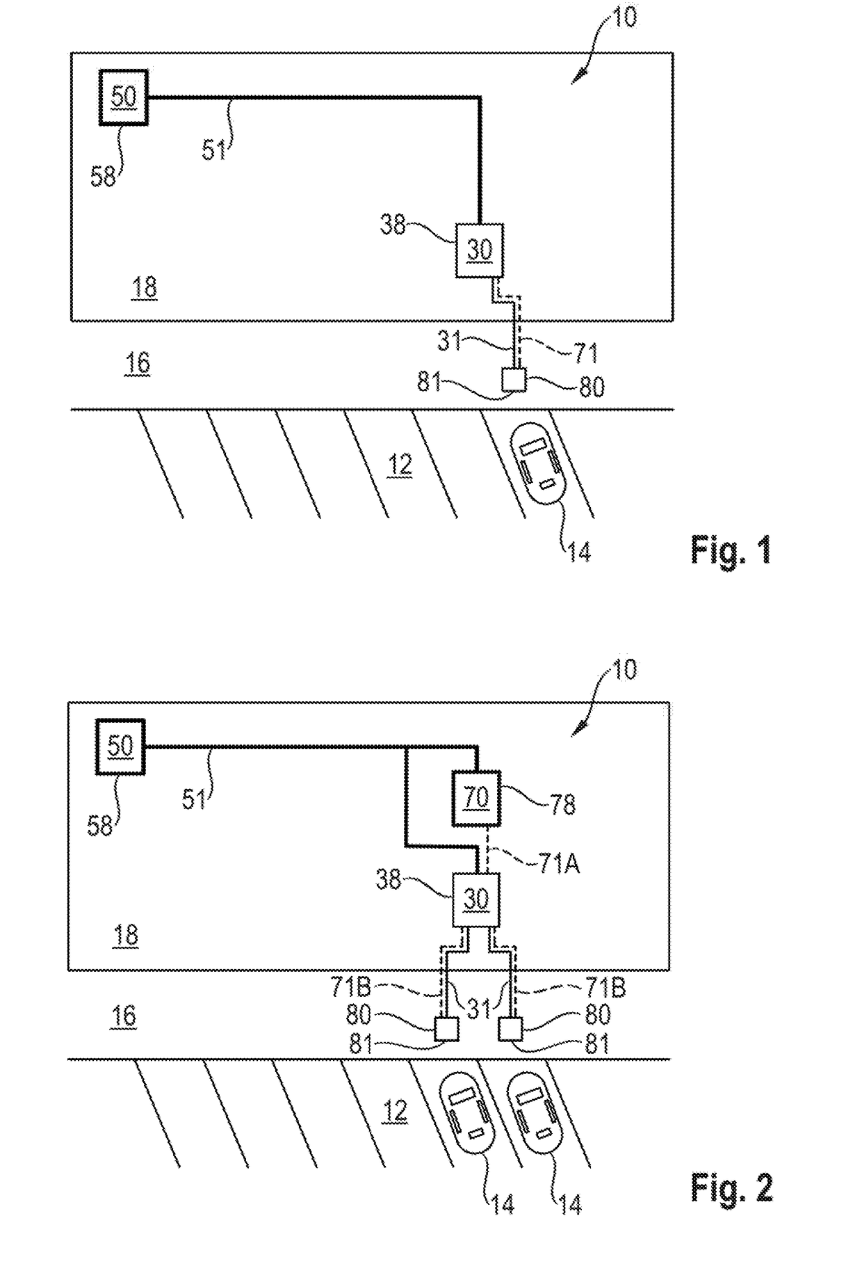
[0059]FIG. 1 shows a device 10 for charging battery of a vehicle 14, in particular for charging a traction battery. Parking spaces 12 are shown schematically on which a vehicle 14 or a plurality of vehicles 14 can be parked. For example, a side walk 16 is provided and an area 18, for example a gravel area or a garden area, is provided on the side of the side walk 16 facing away from the parking spaces 12.

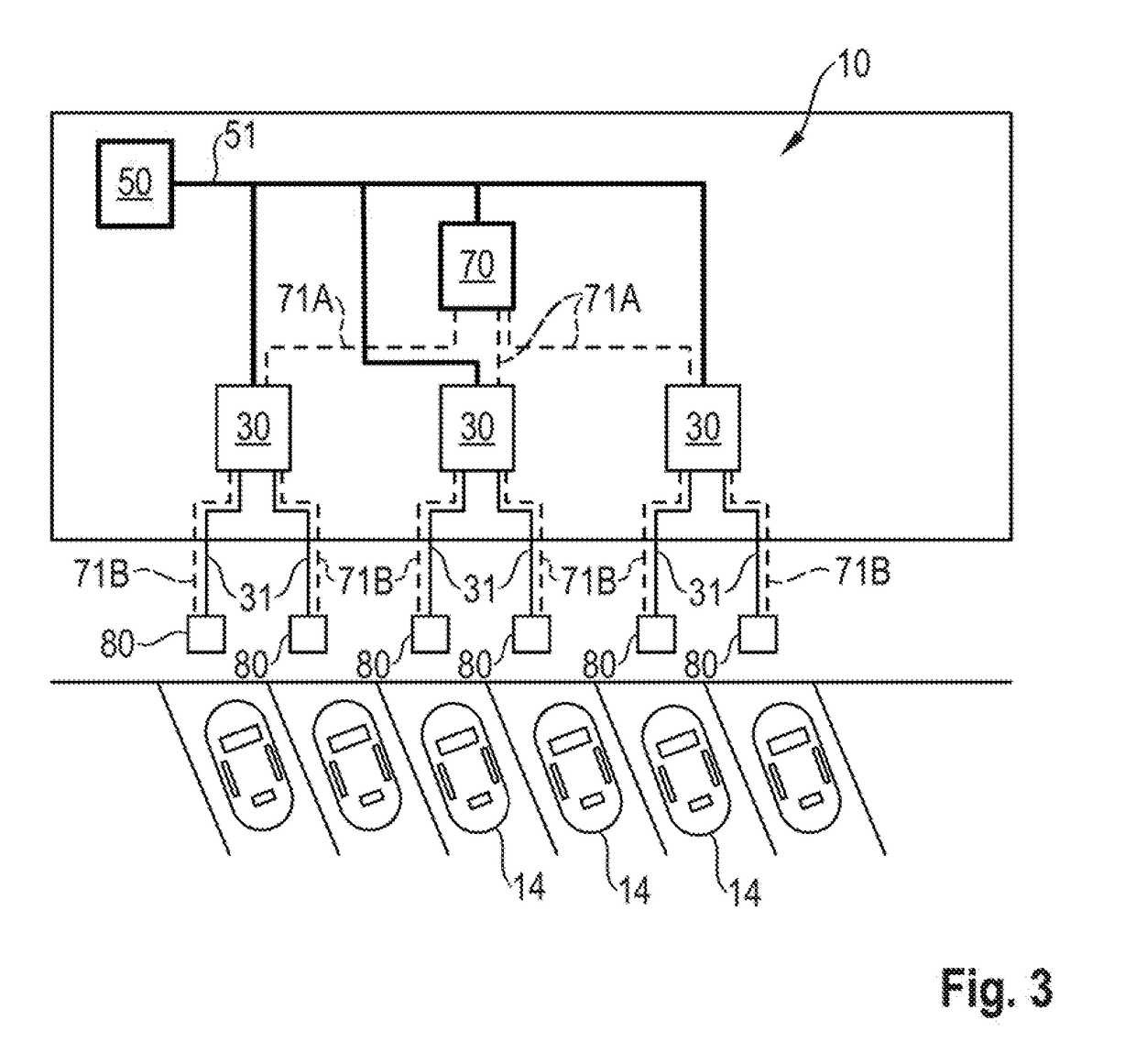
[0060]The device 10 has a transformer module 50 which is connected to an electronics module 30 via an electrical line 51. The electronics module 30 is connected to a charging pillar 80 via an electrical line 31 and via a coolant line 71. The coolant line 71 is illustrated with dashed lines. The charging pillar 80 has a charging point 81. The electronics mod...


PUM


Abstract

A device for charging at least one battery has an electronics module and at least one charging pillar with a charging point. The electronics module has at least one power electronics unit having an AC / DC converter and a DC / DC converter, wherein the electronics module and the at least one charging pillar are spatially separate from one another.

Description

CROSS-REFERENCE TO RELATED APPLICATIONS[0001]This application claims priority to German Patent Application No. DE 10 2017 115 631.3, filed Jul. 12, 2017, which is incorporated by reference herein in its entirety.FIELD OF THE INVENTION[0002]The invention relates to a device for charging at least one battery, in particular or vehicles with an electric drive.BACKGROUND OF THE INVENTION[0003]GB 2 536 653A, which is incorporated by reference herein, presents a direct current capacity supply with a rectifier and a multiplicity of direct current output stages for charging batteries with a high charging capacity.[0004]U.S. Pat. No. 5,594,315, which is incorporated by reference herein, presents an induction charging device for charging a battery. The induction charging device has a primary winding which is connected to a voltage source in order, to generate a magnetic flux, and it has cooling lines through which liquid coolant, fed by a pump, flows in order to cool the induction charging dev...

Claims


Application Information

Patent Timeline
Patent Type & Authority Applications(United States)
IPC IPC(8): B60L11/18H05K7/20
CPCB60L11/1825H05K7/20927B60L2240/36B60L2210/30B60L2210/10B60L53/31H02J7/02H02J7/0013B60L53/14B60L53/32B60L53/11B60L53/18B60L53/302H02J2310/48Y02T10/72Y02T10/70Y02T90/14Y02T10/7072Y02T90/12B60L53/20
Inventor ZIES, CAMILAKOHLER, DAVIDHEYNE, RAOULREBER, VOLKERBASHA, BEKIMROGGENDORF, CHRISTOPHHAHRE, KARSTENGOTZ, STEFANKIEFER, MICHAELZANDER, STEVEMETZGER, CHRISTIAN
Owner DR ING H C F PORSCHE AG
Why Eureka
Try Eureka