
Recording current control method and magnetic disk drive

a current control method and magnetic disk technology, applied in the field of magnetic disk drives, can solve the problem of too high and achieve the effect of reducing the floating height of the magnetic head

Inactive Publication Date: 2006-04-04
HITACHI GLOBAL STORAGE TECH JAPAN LTD
View PDF9 Cites 12 Cited by
  • Summary
  • Abstract
  • Description
  • Claims
  • Application Information

AI Technical Summary

Benefits of technology

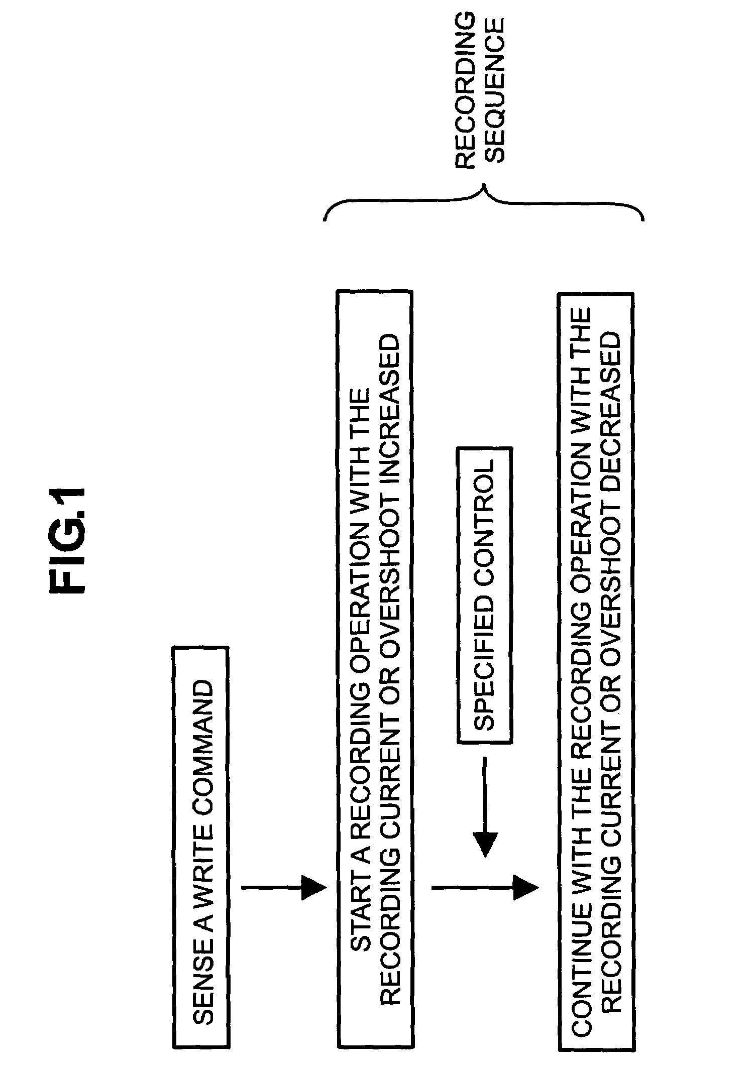
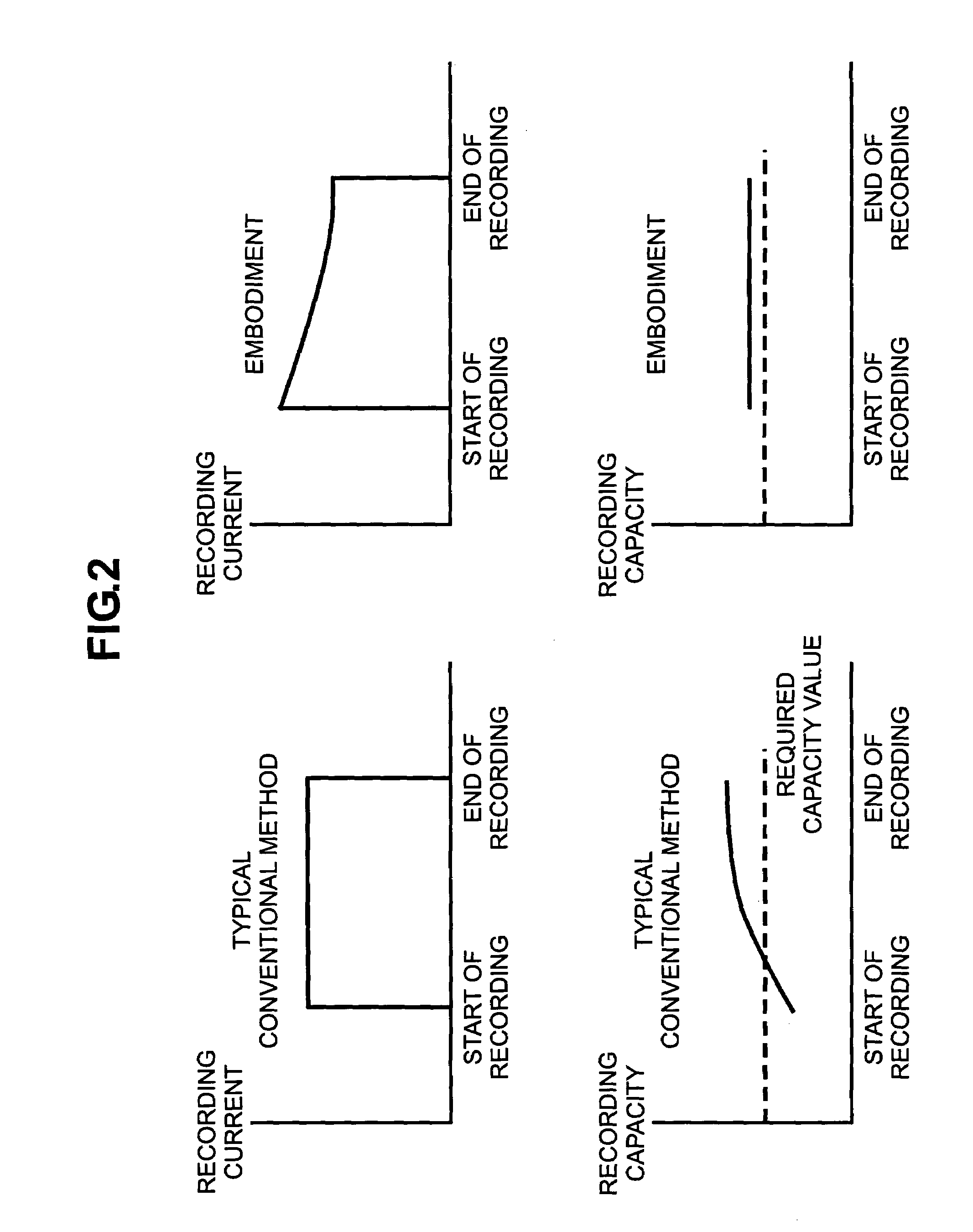
[0013]The applied write current can be decreased smoothly over the write operation, or can transition from a first higher value to a second lower value, where the first and second values are maintained generally constant over significant portions of the write operation. Thus, errors may be reduced or eliminated by writing the first several sectors with the write current increased, and writing the subsequent sectors with the write current decreased.
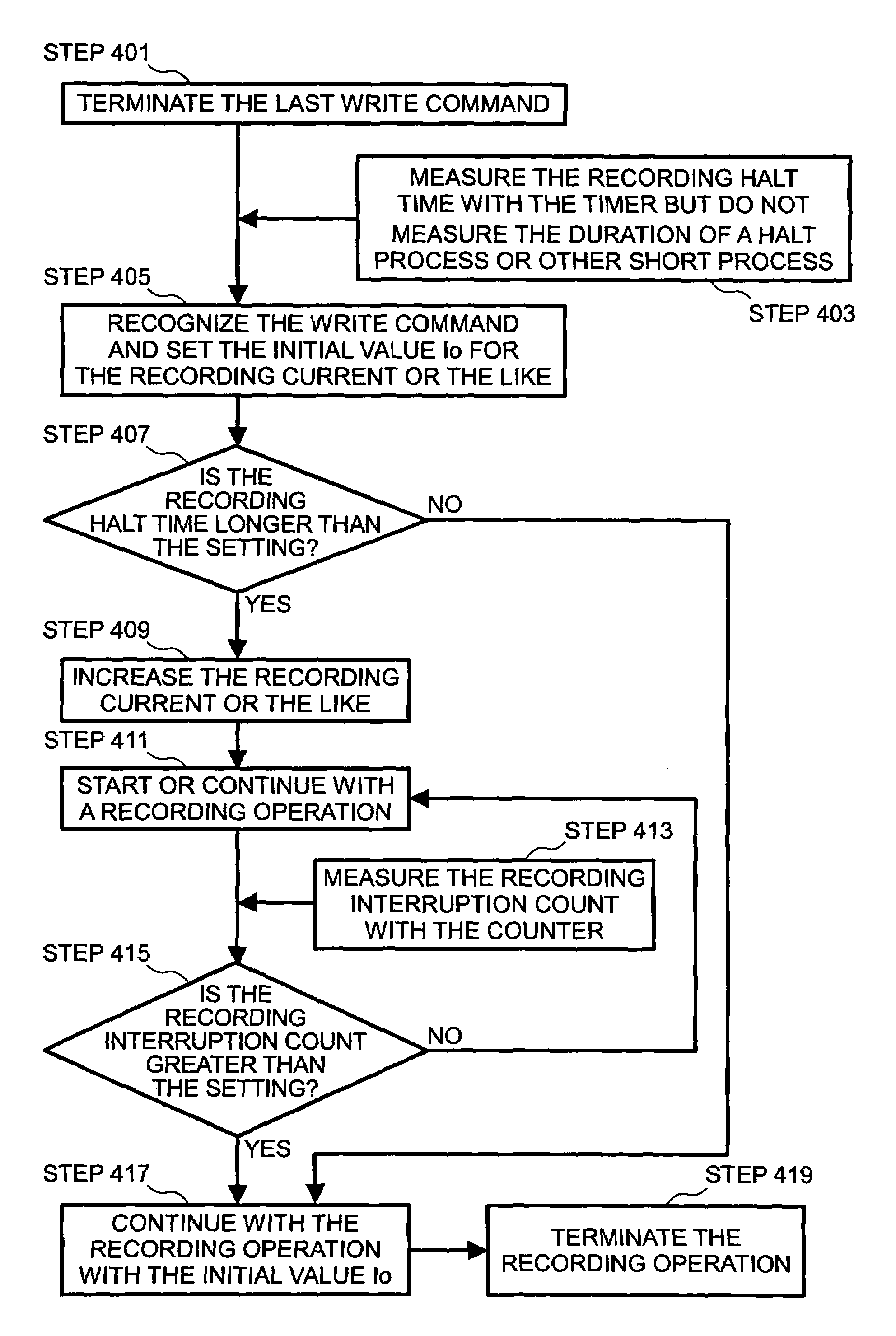
[0014]In another aspect of the invention, a write operation is started, beginning with a target sector, with a relatively large write current setting employed to provide a stronger magnetic field. The write operation is performed in this manner while heating the coil. The write current is reduced later when a predetermined sector is reached or a predetermined period of time elapses. The normal write current setting is relatively raised in accordance with the floating height of the magnetic head for the start of a write. When a write operation begins with a target sector, the above relatively high write current setting is used. The write current may be reduced later when a predetermined sector is reached or a predetermined period of time elapses.
[0016]In another aspect of the invention, the normal write operation is performed while the write coil is energized at a relatively high write current setting to heat the magnetic head write coil and its surrounding area and decrease the floating height of the magnetic head.

Problems solved by technology

Therefore, the resulting data write may be inadequate so that a read error occurs when an attempt is made later to read the written data.
Further, when the write current begins to flow to the magnetic head the moment the magnetic head arrives at a target sector, a write operation begins with the target sector although the floating height of the magnetic head is too high.

Method used


Image

  • Recording current control method and magnetic disk drive
  • Recording current control method and magnetic disk drive
  • Recording current control method and magnetic disk drive

Examples


Embodiment Construction

[0026]As will be described in greater detail below, embodiments of the invention provide for controlling the increase / decrease in the write current or overshoot for individual information segments. In other words, the write capacity is increased for individual information segments. The individual information segments are divisions into which the information to be written is divided. A sector is a typical example of an information segment.

[0027]The normal write current or overshoot setting may be relatively low. However, the write current or overshoot is preferably increased at an early stage of a write operation. The write current or overshoot may be decreased after a specified sector is written. The normal write current or overshoot setting may be relatively high. However, the write current or overshoot is preferably decreased at a later stage of a write operation, such as after a specified sector is written.

[0028]Some embodiments provide a threshold setup for specifying whether or...


PUM

PropertyMeasurementUnit
timeaaaaaaaaaa
write currentaaaaaaaaaa
timeaaaaaaaaaa

Abstract

In a magnetic disk drive, a writing element and its surrounding area thermally expand due to the heat generated by a write head coil. The transient phenomenon of such thermal expansion may invoke the transient phenomenon of inadequate writing capacity, thereby causing a writing error at an early stage of a write operation. Control is provided which increases / decreases either or both the write current to be applied to a write head and the amount of its overshoot on an individual sector basis during a writing sequence.

Description

CROSS-REFERENCE TO RELATED APPLICATIONS[0001]This application claims priority to Japanese Patent Application No. 2003-074811, filed Mar. 19, 2003, the entire disclosure of which is incorporated by reference for all purposes.BACKGROUND OF THE INVENTION[0002]The present invention relates generally to magnetic disk drives, and more particularly to the control of operating parameters during a write (recording) operation.[0003]Magnetic disk drives are normally connected to a computer, server, or other electronic device, and are frequently used as large-capacity external storage devices. Performance demands are particularly high in a server environment, and a magnetic disk drive connected to a server is required to achieve data transfer at a high speed and exhibit high reliability. The demands on data write frequency and storage capacity are on the increase. To meet high performance requirements at a specified ambient temperature while offering an increased density, it is naturally demand...

Claims


Application Information

Patent Timeline
Patent Type & Authority Patents(United States)
IPC IPC(8): G11B5/02G11B5/09
CPCG11B5/09
Inventor DOI, TAKESHISHIMOKOSHI, MASAYOSHIYOSHIDA, HITOSHI
Owner HITACHI GLOBAL STORAGE TECH JAPAN LTD
Learn More