Braking control apparatus

a technology of braking control and control apparatus, which is applied in the direction of braking systems, braking components, transportation and packaging, etc., can solve the problems of inferior pedal feeling, and achieve the effect of reducing the effect in the initial phase of pedal strok

Inactive Publication Date: 2010-11-25
TOYOTA JIDOSHA KK
View PDF5 Cites 14 Cited by
  • Summary
  • Abstract
  • Description
  • Claims
  • Application Information

AI Technical Summary

Benefits of technology

[0020]The present invention reduces the effects in the initi

Problems solved by technology

At this time, a resistance from the stroke simulator is transmitted to the brake pedal, and consequently a bump can often be felt especially at a sudden braking, thus making pedal feeling i

Method used


Image

  • Braking control apparatus
  • Braking control apparatus
  • Braking control apparatus

Examples


Embodiment Construction

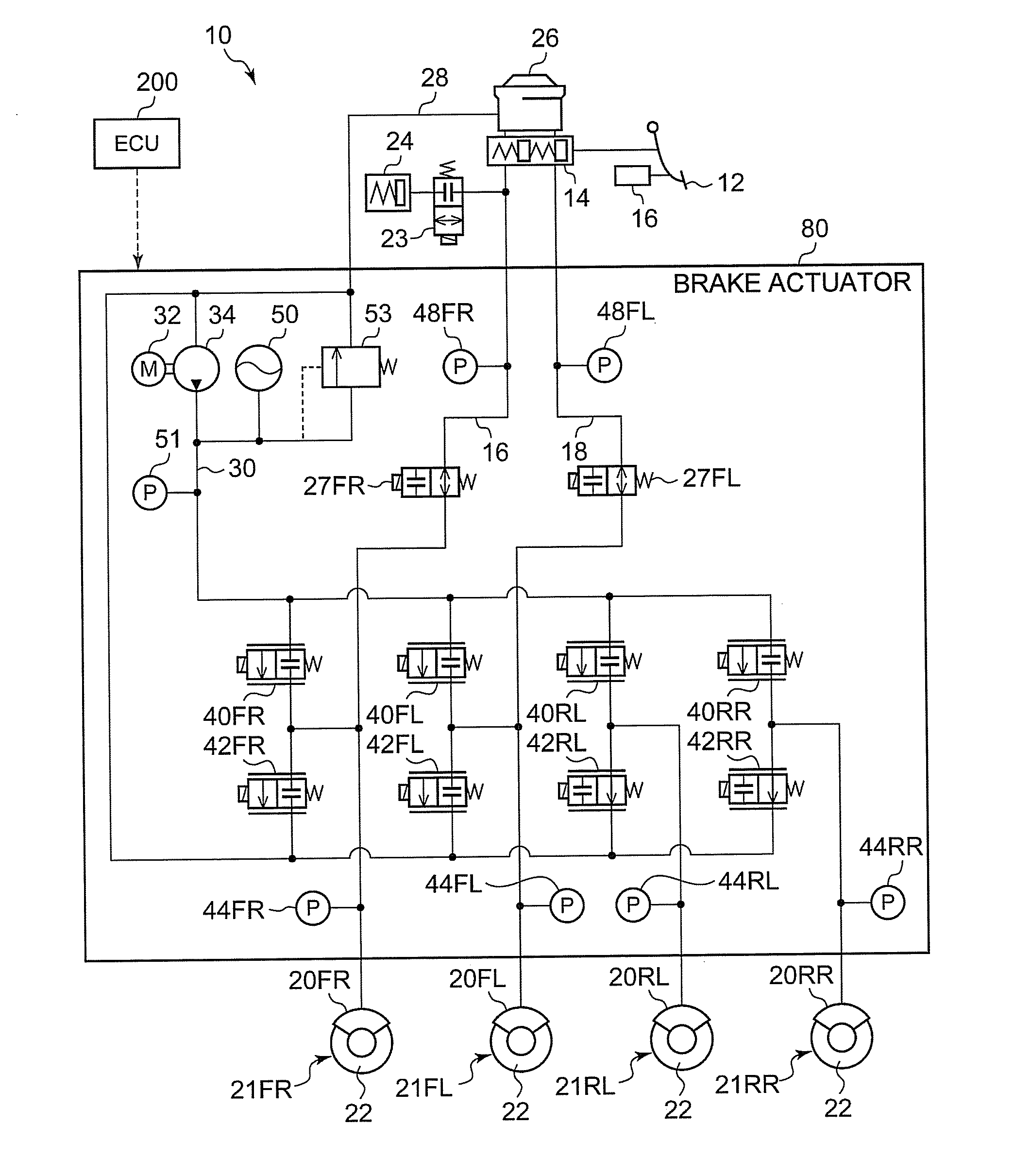
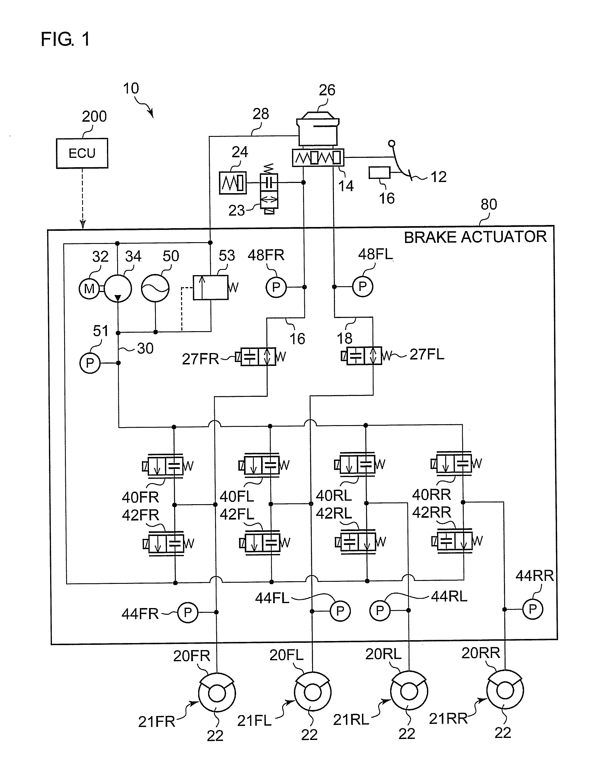
[0029]FIG. 1 is a system diagram showing a brake control apparatus 10 according to an embodiment of the present invention. The brake control apparatus 10 shown in FIG. 1 constitutes an electronically controlled brake system for a vehicle and is capable of making independent and optimal settings for the brakes on the four wheels of a vehicle in response to a driver's operation of a brake pedal 12, which serves as a brake operation member. A vehicle equipped with the brake control apparatus 10 according to the present embodiment is provided with a not-shown steering apparatus for steering the steering wheels of the four wheels, not-shown running drive sources, such as an internal-combustion engine and a motor, for driving the drive wheels of the four wheels, and so forth.

[0030]The brake control apparatus 10 according to the present embodiment is mounted on a hybrid vehicle which is equipped with an electric motor and an internal-combustion engine, for instance, as the running drive so...


PUM


Abstract

A master cylinder includes a first piston, a second piston, and a cylinder for housing the first piston and the second piston slidably in the axial direction. A first fluid pressure chamber, having a passage communicating with a reservoir tank, generates the fluid pressure when communication with the reservoir tank is interrupted at displacement of the first piston by a first stroke. Similarly, a second fluid pressure chamber, having a passage communicating with the reservoir tank, generates the fluid pressure when communi9cation with the reservoir tank is interrupted at displacement of the second piston by a second stroke which is smaller than the first stroke. A stroke simulator communicates with the fluid pressure chamber. A braking control apparatus is structured such that the second piston is first displaced when a brake pedal is pressed.

Description

BACKGROUND OF THE INVENTION[0001]1. Field of the Invention[0002]The present invention relates to a braking control apparatus including a master cylinder which supplies a brake fluid pressure to a wheel cylinder provided on each wheel of a vehicle and a stroke simulator which creates a pedal feeling.[0003]2. Description of the Related Art[0004]It has heretofore been known that, in by-wire brake systems such as ECB (Electrically Controlled Brake) systems, target deceleration is calculated based on the pedal stroke of a brake pedal and the master cylinder pressure. And connected to the master cylinder of such systems is a stroke simulator which gives a driver a pedal feeling by producing a reaction force in the brake pedal.[0005]Patent Document 1 discloses a tandem-type master cylinder apparatus having a first piston and a second piston. In this tandem-type master cylinder apparatus, a first fluid pressure chamber and a second fluid pressure chamber, the former being closer to the brak...

Claims


Application Information

Patent Timeline
IPC IPC(8): B60T13/70
CPCB60T7/042B60T2270/604B60T8/4081B60T8/38
Inventor NIMURA, KAZUNORI
Owner TOYOTA JIDOSHA KK
Why Eureka
Try Eureka