Supercharge Your Innovation With Domain-Expert AI Agents!

Head position detector with optical slit pattern

a detector and optical slit pattern technology, applied in the direction of maintaining head carrier alignment, track following on tape, instruments, etc., can solve the problems of mechanism not being able to determine whether the drive is unplugged, broken head mechanism,

Inactive Publication Date: 2009-07-07
INT BUSINESS MASCH CORP
View PDF6 Cites 0 Cited by
  • Summary
  • Abstract
  • Description
  • Claims
  • Application Information

AI Technical Summary

Benefits of technology

Effectively determines and maintains the correct head position within permissible ranges, preventing mechanical damage by accurately identifying and adjusting the head's position relative to the light-blocking shield, ensuring reliable operation even when the device is powered down or unplugged.

Problems solved by technology

The head is sometimes moved out of the permissible range during the search, which may break the head mechanism.
Accordingly, in such a case, the method causes the head to keep moving in the direction away from the bottom even over the range allowed for the head to move, which breaks the head mechanism.
If no response is detected, the mechanism cannot determine whether the drive is unplugged or the photo-interrupter is crossing the light-blocking shield.
If the head is already at the limit of the range allowed for it to move, that movement breaks the head.
This is not the best measure when the height of the device is limited.

Method used


Image

  • Head position detector with optical slit pattern
  • Head position detector with optical slit pattern
  • Head position detector with optical slit pattern

Examples


first exemplary embodiment

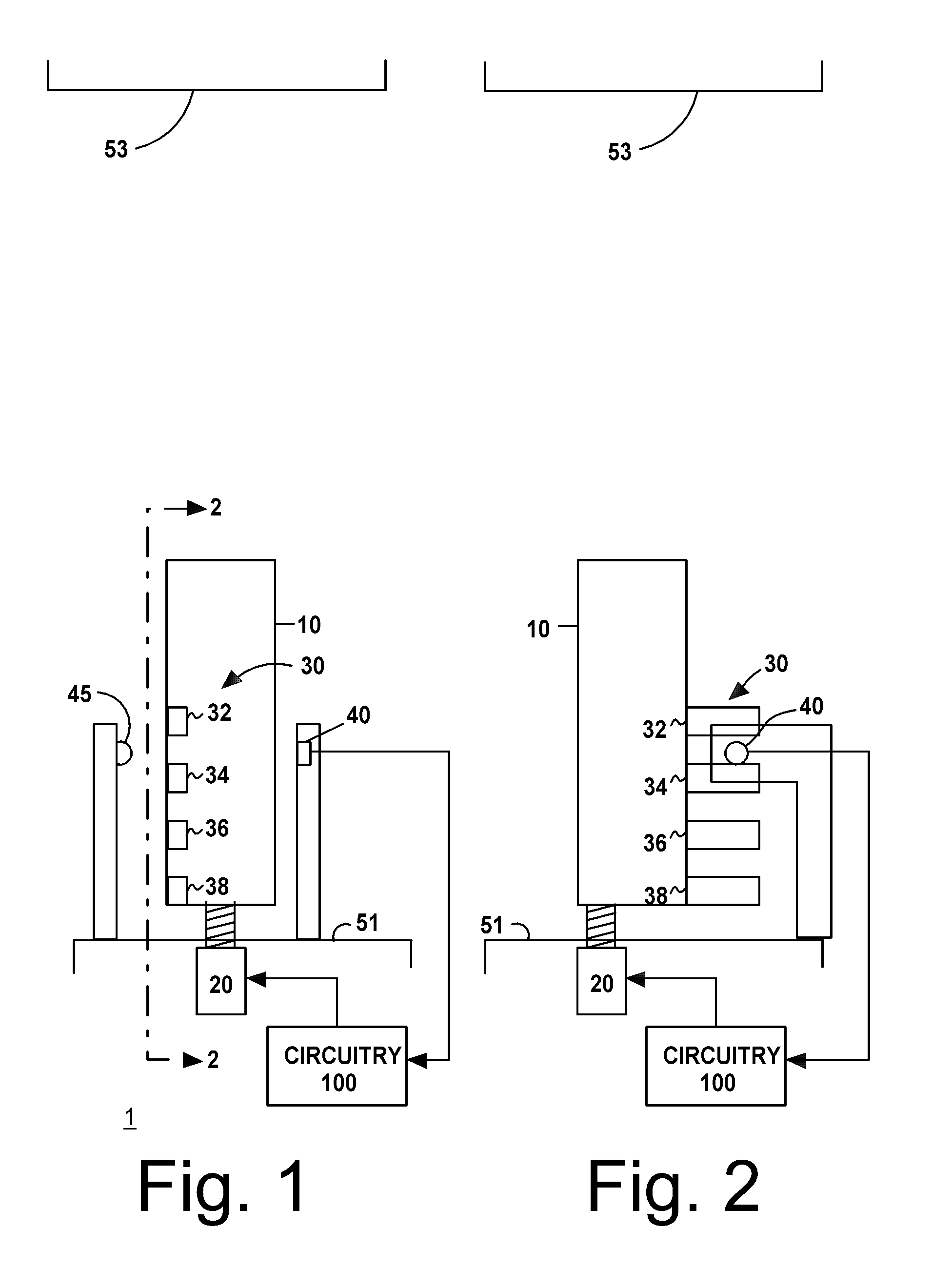
[0017]FIG. 1 shows a first exemplary system 1, including a transducer head body 10, a stepping motor 20 for moving the head body 10, a photo detector 40 configured to receive light from the light source 45, and a light blocking shield 30. The light blocking shield 30 includes projections 32, 34, 36, and 38 that define slits between the projections.

[0018]FIG. 2 is a view taken along the line 2-2 and FIG. 1.

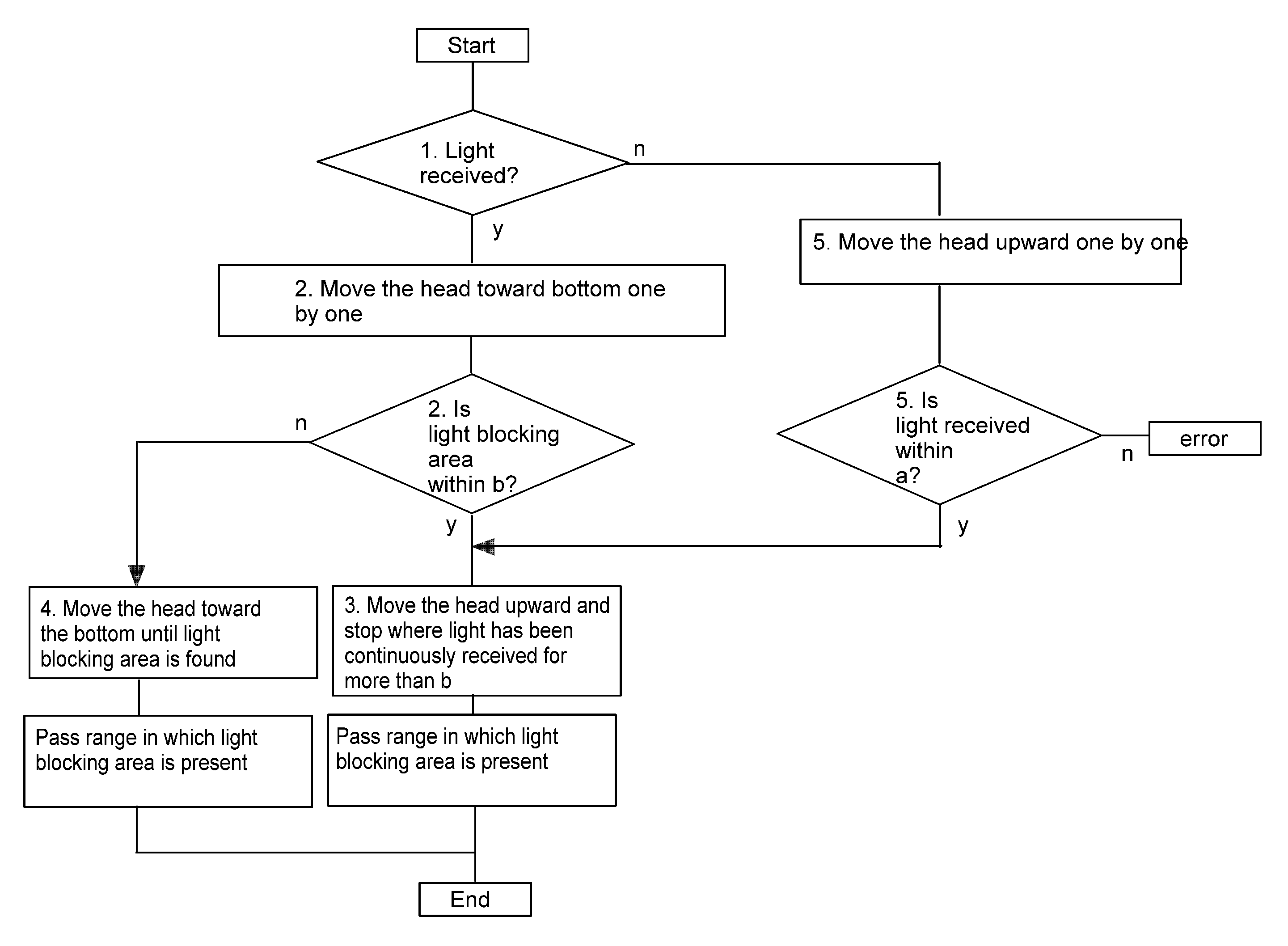
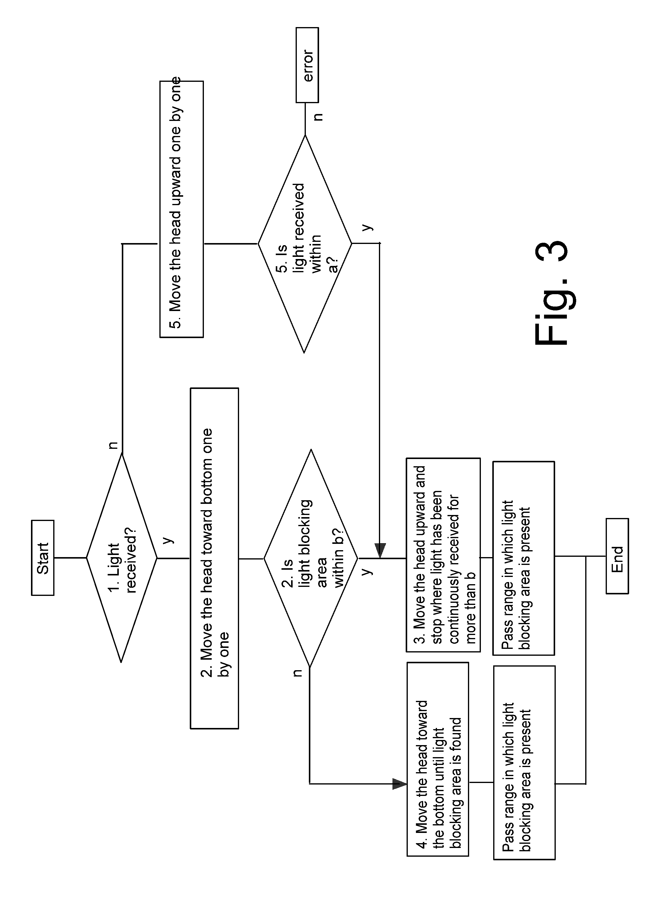
[0019]Stepping motor 20 moves head 10 between the case bottom 51 and the case top 53. When transducer head 10 is near the case bottom 51, projections 32, 34, 36, and 38 act to block the light received by photo detector 40.

[0020]In the description of the first exemplary embodiment, the width of the projections is a, and the slit width between the projections is b.

[0021]The photo detector 40 is attached to the case bottom 51.

[0022]The distance the head 10 moves when 1 pulse is applied to the stepping motor 2 is 1. The slits on the light-blocking shield 30 are such that the width of t...

second exemplary embodiment

[0036]The light-blocking shields are attached across the whole range of the head.

[0037]The width of the aperture differs according to the place. Specifically, the width of the nth aperture is like

bn=b1+d*n

[0038]Then, the current head position can be determined when the head is moved and the width of the nearest aperture is measured. By taking advantage of that, a difference of position due to loss of synchronization of the stepping motor can be corrected.

[0039]Throughout this patent application, certain processing may be depicted in serial, parallel, or other fashion, for ease of description. Actual hardware and software realizations, however, may be varied depending on desired optimizations apparent to one of ordinary skill in the art.

[0040]In this patent application, the word circuitry encompasses dedicated hardware, and / or programmable hardware, such as a central processing unit (CPU) or reconfigurable logic array, in combination with programming data, such as sequentially fetch...


PUM

PropertyMeasurementUnit
widthaaaaaaaaaa
distanceaaaaaaaaaa
poweraaaaaaaaaa

Abstract

Disclosed are systems and methods for positioning a head. An exemplary system includes a light source; a detector configured to receive signals from the light source; a transducer that reads signals from a magnetic tape; a plurality of structures coupled to the transducer and configured to pass in opposition to the detector; a stepping motor; and circuitry configured to determine whether or not a light signal is received by the detector. If the light signal is received, the circuitry commands the stepping motor to move the transducer incrementally in a first direction. If the light signal is interrupted by moving the transducer within a first distance, the circuitry commands the stepping motor to move the transducer in a direction opposite the first direction until the light signal has been continuously received across more than the first distance. If the light signal is not interrupted by moving the transducer within the first distance, continue to the circuitry commands the stepping motor to move the transducer incrementally in a first direction until the light signal is interrupted. If the first determining step determines that the light signal is not received, the circuitry commands the stepping motor to move the transducer incrementally in a direction opposite the first direction.

Description

[0001]This application is a continuation of U.S. application Ser. No. 12 / 058,744 of SHUHEI NADEHARA filed Mar. 30, 2008 now U.S. Pat. No. 7,463,444 for HEAD POSITION DETECTOR WITH OPTICAL SLIT PATTERN, the contents of which are herein incorporated by reference.BACKGROUND OF THE INVENTION[0002]1. Field of the Invention[0003]This invention relates generally to systems and methods for positioning and, more particularly, to systems and methods of positioning a transducer in a storage device such as a tape drive.[0004]2. Description of Related Art[0005]The 3584 LTO drive head is positioned based on the bottom position as a reference position and moves to a specified position with a stepping motor. The position of the head is unknown when the drive is switched on. Then, the bottom position is sought while the head is moved. The head is sometimes moved out of the permissible range during the search, which may break the head mechanism.[0006]Specifically, the conventional 3854 LTO drive has ...

Claims


Application Information

Patent Timeline
Patent Type & Authority Patents(United States)
IPC IPC(8): G11B21/02G11B5/584
CPCG11B5/5504
Inventor NADEHARA, SHUHEI
Owner INT BUSINESS MASCH CORP
Features
  • R&D
  • Intellectual Property
  • Life Sciences
  • Materials
  • Tech Scout
  • Unparalleled Data Quality
  • Higher Quality Content
  • 60% Fewer Hallucinations
Learn More