Proximity detector comprising capacitive sensor

Active Publication Date: 2009-08-04
FOGALE NANOTECH SA +1
View PDF29 Cites 66 Cited by
  • Summary
  • Abstract
  • Description
  • Claims
  • Application Information

AI Technical Summary

Benefits of technology

[0013]A principal objective of the present invention is to propose a proximity detector employing a capacitive sensor which provides accurate measurement (typically to the nearest millimeter) of the position of an object at a measured range (typically to an accuracy of some 10 centimeters) greater than that permitted by proximity det

Problems solved by technology

Generally, an emergency shutdown comprising mechanical circuit breakers stops all movement when the X-ray detector or emitter comes into contact with the patient or another part of the equipment; however, the kinetics of moving objects and the short travel of the contactors requires low displacement

Method used


Image

  • Proximity detector comprising capacitive sensor
  • Proximity detector comprising capacitive sensor
  • Proximity detector comprising capacitive sensor

Examples


Embodiment Construction

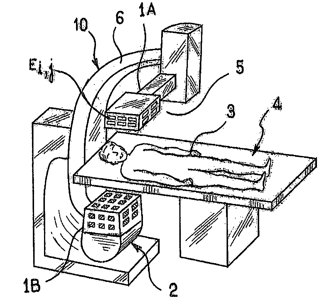
[0049]There will now be described, with reference to FIG. 1, an embodiment of proximity detectors according to the invention in an X-ray radiology machine for a vascular positioner.

[0050]A first proximity detector (1A) is arranged inside an X-ray detector device (5) fitted to a radiology machine (10), and comprising several antennas lining five of the internal or external walls of the cap of the X-ray detector, each antenna comprising a plurality of electrodes Ei,j. A second proximity detector (1B) is arranged on the inside surface of the X-ray emitter device of the machine (10). The X-ray emitter device (2) and the X-ray detector device (5) are installed at the two ends of a C-shaped moving part rotating around an examination table (4) on which a patient (3) is lying.

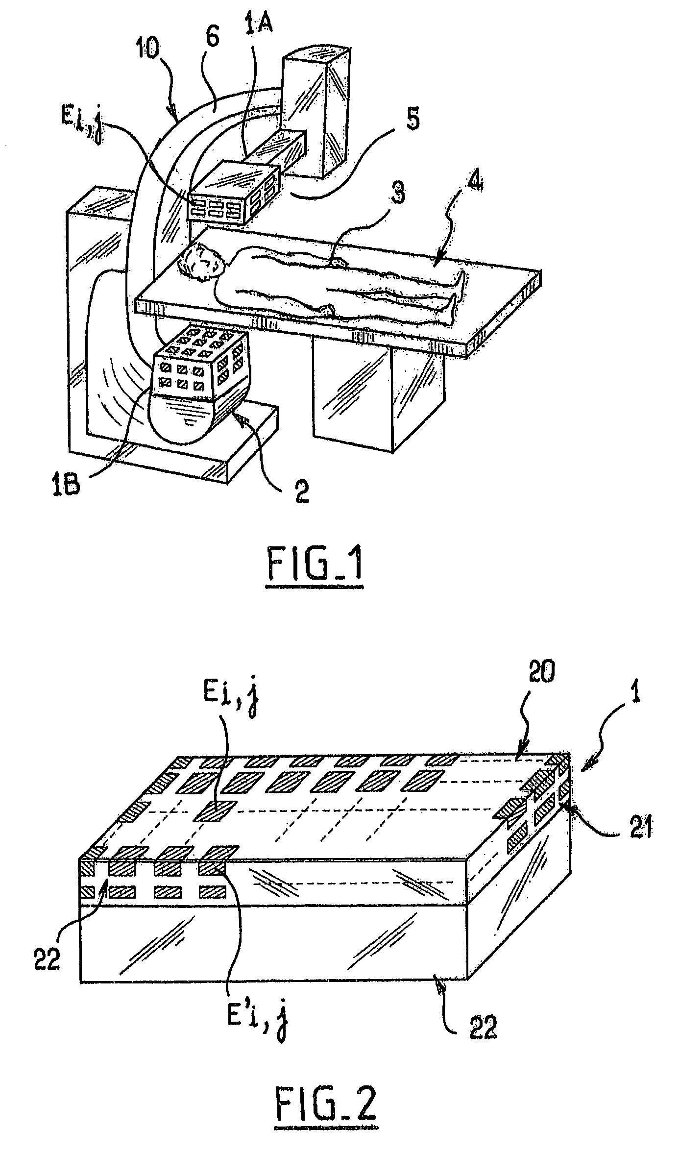
[0051]By reference to FIG. 2, a proximity detector according to the invention 1 comprises an antenna 20 arranged on the inside surface of the cap 22 and the side faces 21, 22. The antenna 20 is constituted by a plurali...


PUM


Abstract

A proximity detector employs a capacitive sensor, having: at least one detection antenna including numerous capacitive proximity sensors which each include a measuring electrode, the antenna being positioned close to an object or body; electronic elements for exciting the electrodes and processing the distance measurement signals originating from the capacitive sensors; and digital elements of controlling the electronic elements and of calculating the distances between the electrodes and the body or object using the processed measurement signals. The detection antenna also contains a single guard for all of the measuring electrodes. Moreover, the electronic elements have, for each detection antenna, a floating or floating excitation capacitive bridge which co-operates with polling elements in order sequentially to measure the respective capacitances between each electrode and the object or body to be measured.

Description

BACKGROUND OF THE INVENTION[0001]The present invention relates to a proximity detector employing a capacitive sensor.[0002]In a numerous industrial applications, the proximity between a machine and an obstacle must be detected and measured, whether this is another object or an individual, in order to deliver proximity distance information, alarm signals and to act as a result.[0003]By way of non-limitative example, the industrial application of this type of detector which can be mentioned is the management of an anti-collision function between mobile or stationary robots and an obstacle, management of an anti-burglary function and, more generally, any management implementing proximity detection.[0004]In the medical field, various robots used for the auscultation of patients need to know the position of the patient relative to the moving parts of the machine.[0005]By way of example, for applications in radiology or in imaging, or also for a medical or surgical treatment, it is essent...

Claims


Application Information

Patent Timeline
IPC IPC(8): G01R27/26A61B5/103A61B5/117G01B7/00A61B6/10G01B7/02G01V3/08H03K17/955
CPCA61B6/102G01B7/023H03K17/955
Inventor ROZIERE, DIDIER
Owner FOGALE NANOTECH SA
Why Eureka
Try Eureka