Paving convoy

a technology of convoys and paving, which is applied in the direction of temporary pavings, roads, construction, etc., can solve the problems of complicated cleaning work, high cost, and complicated structure, and achieve the effect of fair cos

Active Publication Date: 2009-08-11
JOSEPH VOEGELE AG
View PDF46 Cites 30 Cited by
  • Summary
  • Abstract
  • Description
  • Claims
  • Application Information

AI Technical Summary

Benefits of technology

[0007]It is an object of the invention to provide a paving convoy as mentioned above which is a modularly constructed system with standard machines for carrying out paving work with and without a bitumen emulsion binding layer and which allows the reduction of basic costs.
[0008]For paving work needing a binding layer, the spraying nozzle is installed between the feeding assembly, e.g. constituted by a standard shuttle buggy, and the standard road paver for deploying the bitumen emulsion binder layer in front of the road paver on the planum. Neither the standard shuttle buggy nor the standard road paver then need complicated retrofit work. In the case that a binder layer is not needed, the spraying module is dispensed with and paving work is carried out conventionally. The spraying module as a modular component of the paving convoy is a fair cost, versatile and efficient supplementary machine. Between the spraying module which does not have its own traction drive and the shuttle buggy is either provided with a towing connection which can be detached to remove the spraying module, the towing connection forcing the spraying module to travel with the shuttle buggy, or a pushing connection is provided between the spraying module which does not have its own traction drive and the road paver such that the road paver pushes the spraying module on the undercarriage with a predetermined distance in-between.
[0010]In a further expedient embodiment a power transmission connection and a control signal transmission connection is provided between the spraying module and the shuttle buggy and / or the standard road paver such that the spraying module is supplied with power from one of the machines or from both machines, e.g. used for heating and deploying and metering the bitumen emulsion, or is controlled accordingly. This is a particularly fair cost embodiment of the spraying module. Control systems and power systems provided at the shuttle buggy and / or at the road paver can fulfil such supplementary tasks needed for the operation of the then installed spraying module without problems.

Problems solved by technology

The shuttle buggy with integrated spraying device as well as the road paver with the integrated spraying bars both have individual special designs and are for these reasons structurally complicated and costly.
In cases where no bitumen emulsion is needed, the feeder has to tow the unnecessary ballast of the spraying device, and as well spraying bars on the road paver are unnecessary ballast.
The spraying device and the spraying bars on the road paver are contaminated during normal paving work and for this reason need complicated cleaning work after the termination of the work, irrespective of whether the work was carried out with or without spraying bitumen emulsion.

Method used


Image

  • Paving convoy
  • Paving convoy

Examples


Embodiment Construction

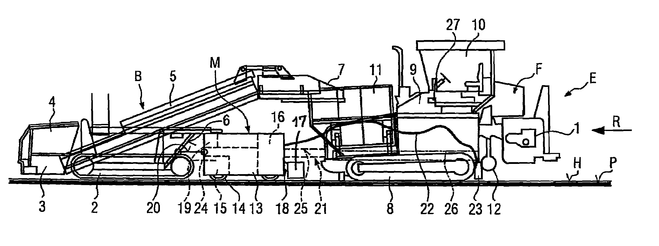
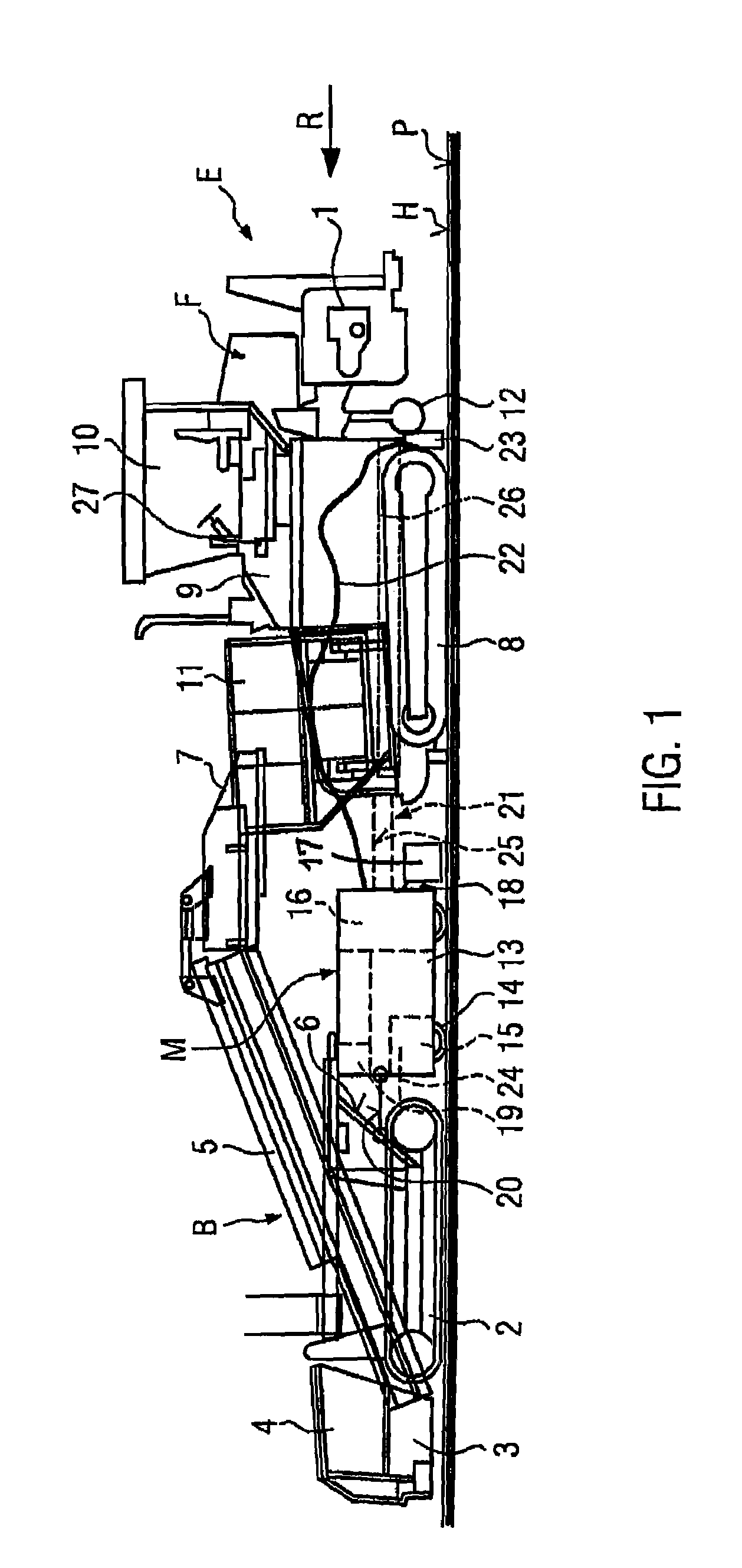
[0015]The paving convey E shown in FIG. 1 in a schematic side view serves to cast on a planum P either a bituminous cover layer (as shown) on a bitumen emulsion binder layer H, or to cast at least one, e.g. bituminous, cover layer without a binder layer H directly on the planum P (the latter case is not shown, but will explained further on).

[0016]The paving convey E comprises a standard road paver F having a towed paving screed 1 (in some cases an extendible paving screed with controlled variable working width) for casting the cover layer, e.g. of bituminous paving material, in a casting travelling direction R, and a paving material feeding assembly B travelling in front of the standard road paver F on the planum. The feeding assembly B is a so-called standard shuttle buggy. Finally, a spraying module M is provided for deploying part of the binder layer H which spraying module M is travelling on the plenum P between the feeding assembly and the standard road paver F.

[0017]The feedin...


PUM


Abstract

A paving convoy for producing a bituminous cover layer including a self-propelled road paver and a paving material feeding assembly which is self-propelled and travels in front of the road paver. A paving material conveying device extends from the feeding assembly to the road paver. A spraying module including its own undercarriage and components for storing and deploying bitumen emulsion is provided between the feeding assembly and the road paver. The spraying module has a spraying bar facing the front end of the road paver. The spraying module is either coupled to the feeder assembly by a detachable towing connection or to the road paver by detachable pulling connection.

Description

FIELD OF THE INVENTION[0001]The invention relates to a paving convoy according to the preamble of claim 1.BACKGROUND OF THE INVENTION[0002]The spraying module of the paving convoy known from JP 2002 322603A is a modified standard truck on which spraying module components are arranged on the bed of the chassis. A spraying bar faces the planum operating behind the rear end of the chassis. The truck has its own traction drive and travels between the road paver travelling behind the feeding assembly travelling ahead. The feeding assembly is supplied from the trucks delivering the paving material.[0003]In the paving convoy known from AT-E-556344 B the spraying device is integrated into the feeding assembly which in turn is constituted by a shuttle buggy. The feeding assembly conveys paving material over the spraying bar of the spraying device to the road paver. The spraying bar sprays a bitumen emulsion within the working width of the paving screed on the planum but leaves the travelling...

Claims


Application Information

Patent Timeline
Patent Type & Authority Patents(United States)
IPC IPC(8): E01C19/21E01C19/08
CPCE01C19/17E01C19/48E01C2301/04
Inventor BUSCHMANN, MARTIN
Owner JOSEPH VOEGELE AG
Why Eureka
Try Eureka