Portable device for viewing and imaging

a portable, light-emitting technology, applied in the field of illumination optical systems, can solve the problems of large loss of light energy, cumbersome operation, unwieldy and difficult to operate, etc., and achieve the effect of significant operational advantages

Inactive Publication Date: 2009-09-01
XENONICS INC
View PDF42 Cites 14 Cited by
  • Summary
  • Abstract
  • Description
  • Claims
  • Application Information

AI Technical Summary

Benefits of technology

[0009]In one aspect, the invention is a compact device that can illuminate objects much farther than the eye can see or reliably resolve. The ability to clearly observe a scene at ranges of approximately 400 meters and farther at nighttime or in low-light conditions or other situations of impaired visibility gives the user a significant operational advantage. It is contemplated that such a system will be beneficial in military, law enforcement, border-patrol, security, and maritime vessel applications, and other applications where a portable, compact device of this kind is desired.
[0011]The present invention is also characterized as a compact, handheld, portable device that can illuminate objects at distances greater than the naked eye can reliably see. The device further provides illumination in either the visible spectrum or infrared spectrums. A telescopic lens system integrated with the illumination system has sufficient capability to view objects from a great distance in both the visible and infrared spectrums. The telescopic lens system can alternatively be applied to a digital camera system. More specifically, the digital camera system may contain an image sensor, such as a charge-coupled device (CCD), and a means to display an image such as a LCD display. The invention alternatively includes an eyepiece lens such that a user may choose to view a display screen or use the eyepiece lens to optically observe the field of view. Because the image is digital, the invention allows for the possibility of real time imaging processing in the portable device, so that the displayed image can be artificially enhanced according to the control of the user to optimize visualization of the image or a selected part thereof. The invention also includes the ability to transmit image data to remote receivers as part of a wireless battlefield.
[0012]The device of the present invention has a light source or a lamp, such as a xenon arc lamp or other plasma lamp; or alternatively the device comprises a high intensity discharge lamp (HID) such as a mercury vapor, metal halide or high pressure sodium lamp. The device of the invention is further characterized in that light energy is produced from a highly concentrated plasma ball, or illumination source, and precisely radiated about a reflector's optical axis of symmetry, wherein light waves can achieve great illumination distances. Alternatively, if a plasma lamp is used, the plasma lamp will have circuitry associated with it to obtain proper voltages for creating and maintaining a glowing plasma. Also, the device including the lamp will have a mechanical configuration including a lamp holder that allows for relatively quick replacement in the field while maintaining the precise alignment necessary for long-range operation.
[0013]Also, the lamp is mounted within the searchlight so that the anode of the lamp is in the rearward position relative to the direction of a beam projected by the searchlight so that the field of illumination of the beam is slightly convergent and more concentrated and therefore delivers a much longer range of operation. This configuration will prevent the “black hole” effect associated with other configurations such as cathode to the rear.

Problems solved by technology

Separate systems for illuminating from a great range while simultaneously observing using a different apparatus, such as a telescopic viewing and imaging system, can be cumbersome, unwieldy and difficult to operate.
One particular problem is finding and maintaining alignment and focus on a particular object that is separately illuminated by another system.
More specifically, focusing with infrared light requires more precise alignment angles for a lamp and a lens as just a couple of degrees difference will result in a loss of a large amount of available light energy.

Method used


Image

  • Portable device for viewing and imaging
  • Portable device for viewing and imaging
  • Portable device for viewing and imaging

Examples


Embodiment Construction

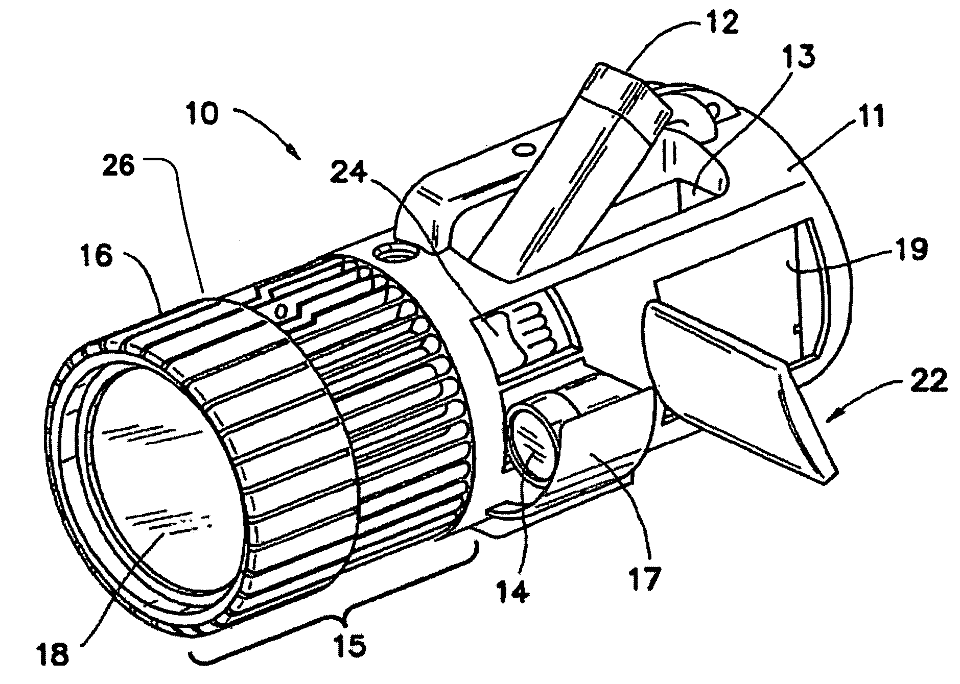
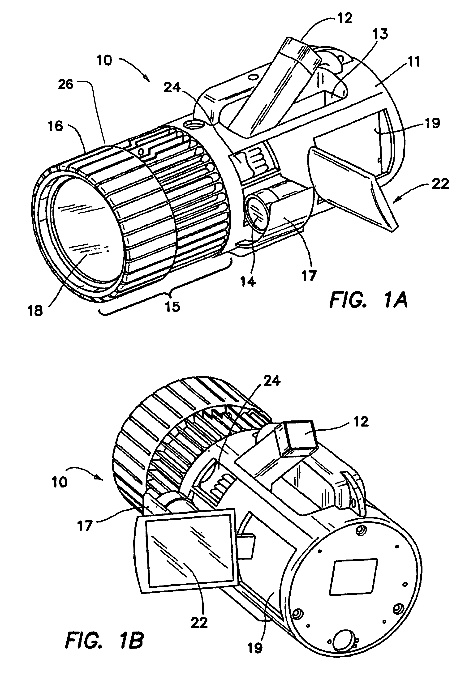
[0022]Now referring to FIGS. 1A and 1B, a compact, handheld device 10 of a preferred embodiment of the present invention is illustrated in front and rear perspective view. Eyepiece viewer 12 has a deployed and a stowed position, which is shown in FIGS. 1A and 1B in the stowed position. Eyepiece viewer 12 is optically coupled to the telescopic lens assembly 14 and can be rotated upward to be deployed at a user-selected angle of convenience or rotated downwardly to lie in a flush configuration within a receiving cavity 13 defined in body 11 of device 10. The actual image which is being optically received by telescopic lens assembly 14 can be directly viewed by the user through eyepiece viewer 12.

[0023]Similarly, telescopic lens 14 has deployed and stowed positions. Lens assembly 14 rotates out of a cavity 24 defined in body 11 for flushly receiving lens assembly 14 as a protective door 17 also moves or rotates out. The mechanical linkage by which such movements can be realized are con...


PUM


Abstract

A portable searchlight with a focused beam operating both in the infrared and visible portions of the spectrum with a range of approximately 400 meters includes telescopic lens system integrated with an illumination system. The beam of the searchlight and the telescopic lens are automatically aligned to both focus on the distant object. The telescopic lens system is combined with a digital camera system and an LCD display. The searchlight includes an eyepiece lens enabling an user to choose either viewing a display screen or using the eyepiece lens to optically observe the field of view.

Description

RELATED APPLICATIONS [0001]The present application is related to U.S. Provisional Patent Application, Ser. No. 60 / 546,812, filed on Feb. 23, 2004, which is incorporated herein by reference and to which priority is claimed pursuant to 35 USC 119. This appication also claims priority to U.S. patent application Ser. No. 10 / 414,936, entitled APPARATUS AND METHOD FOR OPERATING A PORTABLE XENON ARC SEARCHLIGHT, filed Apr. 14, 2003, now U.S. Pat. No. 6,896,392, which is a division of U.S. patent application Ser. No. 09 / 440,105, entitled APPARATUS AND METHOD FOR OPERATING A PORTABLE XENON ARC SEARCHLIGHT, filed Nov. 15, 1999, now U.S. Pat. No. 6,702,452, the entire disclosures of which are hereby incorporated by reference as if being set forth in their entireties herein.BACKGROUND OF THE INVENTION [0002]1. Field of the Invention[0003]The present invention pertains generally to illuminating optical systems, AND more particularly, to a nighttime, long-range, portable illuminating device havin...

Claims


Application Information

Patent Timeline
Patent Type & Authority Patents(United States)
IPC IPC(8): F21V33/00G03B29/00F21L2/00F21S8/00F21V9/00G02B23/00G02B23/12H04N5/225
CPCF21S8/003H04N5/2256G02B23/00G02B23/12F21V33/0052F21V9/00F21V9/20H04N23/56
Inventor KENNEDY, JEFFREY P.MAGERMAN, ALAN P.MADDOX, STEPHEN L.
Owner XENONICS INC
Why Eureka
Try Eureka