Steerable/retractable cargo power drive unit

a power drive unit and retractable technology, applied in the direction of aircraft floors, transportation and packaging, fuselages, etc., can solve the problems of inability to adapt to different applications, limited operational flexibility of prior art pdu's, and heavy weight of complex mechanisms, etc., to achieve the effect of reducing power consumption, reducing weight, and reducing complexity

Active Publication Date: 2010-03-09
ANCRA INTERNATIONAL CORPORATON
View PDF26 Cites 14 Cited by
  • Summary
  • Abstract
  • Description
  • Claims
  • Application Information

AI Technical Summary

Benefits of technology

[0009]An advantage of the present invention is a steerable PDU which is faster, lighter in weight, less costly and has reduced power consumption compared with prior art actuators.
[0010]According to the present invention, the foregoing and other advantages are achieved in part by an apparatus for conveying cargo, the apparatus comprising a stationary support for fixedly attaching to a vehicle structure; a support base; a rotating support for fixedly mounting the support base, the rotating support being rotatably mountable to the fixed support; a drive assembly pivotably mounted to the support base for limited vertical movement substantially normal to the longitudinal axis of the support base, the drive assembly comprising a roller and a first electronically controlled electric motor for rotating the roller; a lift assembly comprising a second electronically controlled electric motor for moving the drive assembly relative to the support base from a retracted position substantially within the support base to an extended position with the roller in driving abutment against the cargo; a rotation drive assembly comprising a third electronically controlled electric motor for rotating the rotating support relative to the stationary support; and an electronic controller for controlling the first, second and third motors.

Problems solved by technology

Prior art PDU's can involve complex mechanisms which are heavy, costly and difficult to repair or replace.
However, regardless of their degree of complexity, prior art PDU's are limited in their operational flexibility under varying conditions, such as use in different vehicles or for different types of cargo containers or loading.
As a result, they are not easily adaptable to different applications.

Method used


Image

  • Steerable/retractable cargo power drive unit
  • Steerable/retractable cargo power drive unit
  • Steerable/retractable cargo power drive unit

Examples


Embodiment Construction

[0023]Conventional PDU's are mechanically complex and lack flexibility under varying operating conditions or vehicles. The present invention addresses and solves these problems of conventional PDU's.

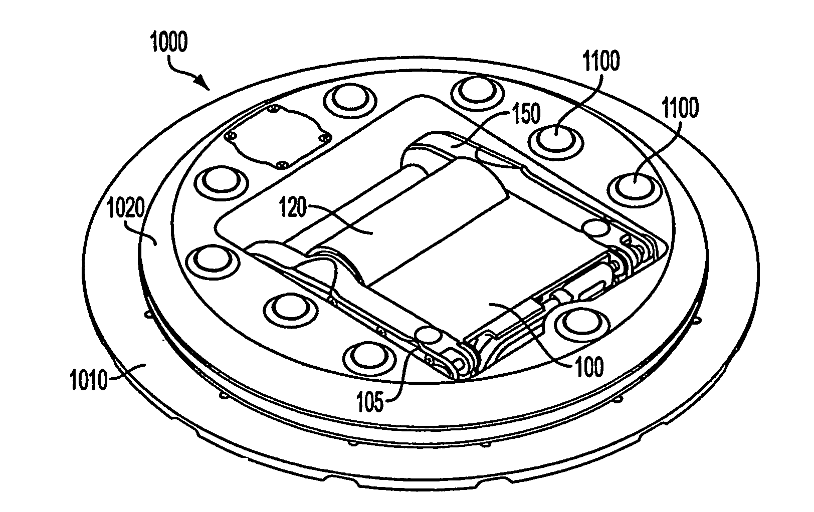
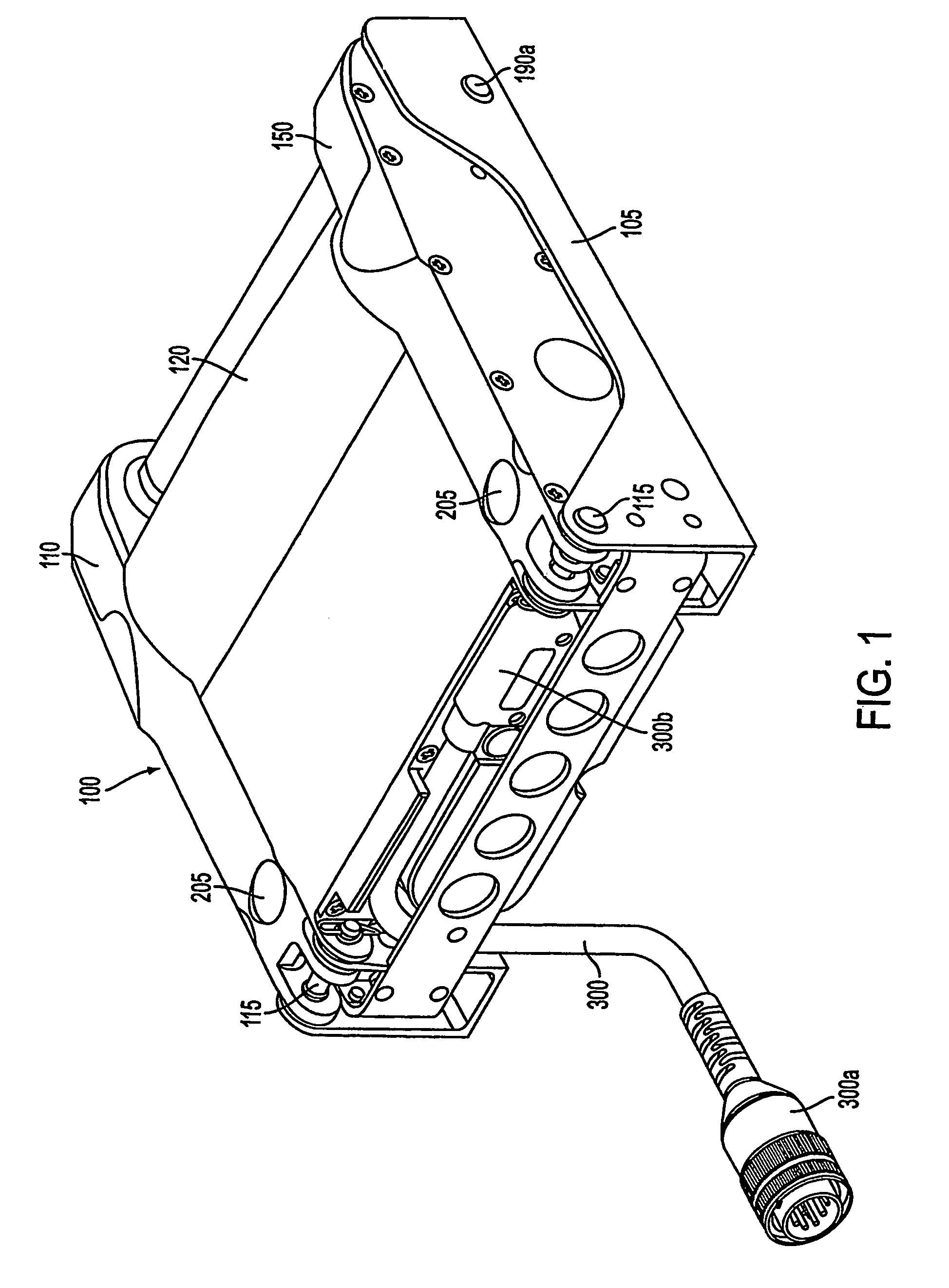
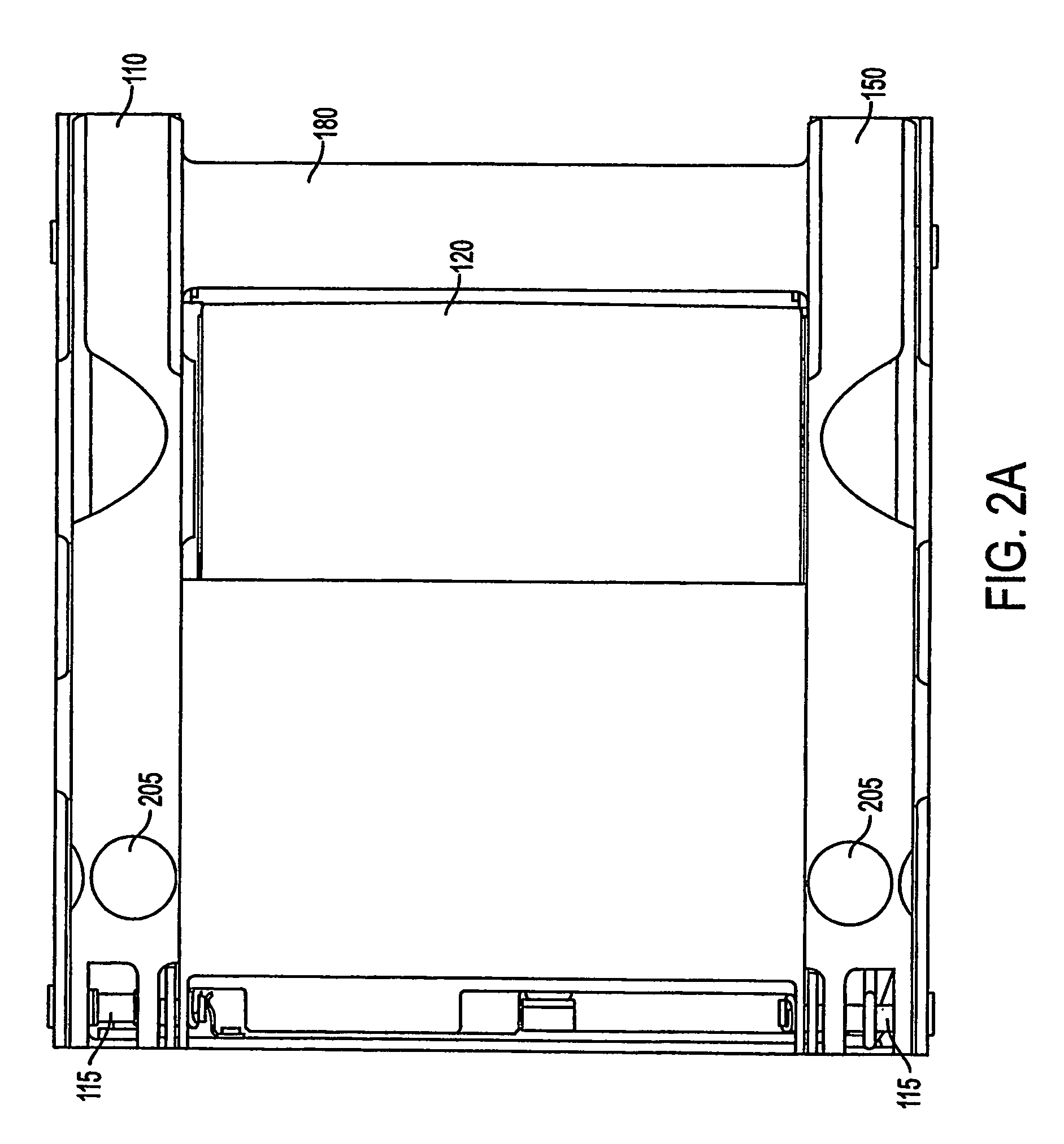
[0024]The actuator of the present invention is commonly called a steerable, retractable power drive unit (SRPDU). It is designed to install into a transport vehicle in areas requiring movement of containers in mutually perpendicular directions, such as a doorway area where containers need to move both laterally and longitudinally in a cargo vehicle. The actuator rotates 90° upon application of an external command, to orient the drive assembly in the required direction and to drive the cargo containers. The actuator can also be commanded to intermediate angular positions to facilitate the rotation of containers. The actuator improves upon the current state of the art by providing rotary actuation and cargo transport which is faster, lighter weight, less costly and with reduced power consu...


PUM


Abstract

A steerable, retractable power drive unit (SRPDU) is provided for installation into a transport vehicle for moving cargo in mutually perpendicular directions, such as a doorway area where containers need to move both laterally and longitudinally in a cargo vehicle. The SRPDU rotates upon application of an external command, to orient the drive unit in the required direction and to drive the cargo containers. Embodiments include an SRPDU comprising a stationary support for fixedly attaching to a vehicle structure, and a rotating support rotatably mounted to the stationary support. A drive assembly is movably mounted to the rotating support, the drive assembly comprising a roller and a first electronically controlled electric motor for rotating the roller. A lift assembly mounted to the drive assembly has a second electronically controlled electric motor for moving the drive assembly relative to the rotating support from a retracted position substantially within the rotating support to an extended position with the roller in driving abutment against the cargo. A rotation drive assembly has a third electronically controlled electric motor on the rotating support for rotating the rotating support relative to the stationary support. An electronic controller controls the first, second and third motors.

Description

[0001]This application is the U.S. National Phase under 35 U.S.C. § 371 of International Application No. PCT / US2004 / 013623, filed Apr. 30, 2004, which in turn claims the benefit of U.S. Application No. 60 / 467,133, filed May 2, 2003, the disclosures of which Applications are incorporated by reference herein in their entirety.FIELD OF THE INVENTION[0002]The present invention relates to cargo conveying systems for use in moving cargo on a vehicle such as an aircraft. The present invention has particular applicability in roller drive systems in which a roller is urged upwardly against cargo to be conveyed when the system is activated and retracted when the system is deactivated.BACKGROUND ART[0003]Roller assemblies which are removably mounted on carriers attached to the floor of a vehicle are widely used for conveying cargo within such vehicles. These roller assemblies or “actuators” are intended for use in systems which involve the transport of commercial and military cargo containers ...

Claims


Application Information

Patent Timeline
Patent Type & Authority Patents(United States)
IPC IPC(8): B64D9/00B65G13/06
CPCB60P1/52B64D9/00B65G13/065B64D2009/006B65G2201/0267Y02T50/46Y02T50/40B65G13/06
Inventor MCCONNELL, MATTHEW S.
Owner ANCRA INTERNATIONAL CORPORATON
Why Eureka
Try Eureka