Workpiece-transporting apparatus of in-line sputtering machine

a technology of in-line sputtering machine and transporting apparatus, which is applied in the direction of transportation and packaging, manufacturing tools, vacuum evaporation coating, etc., can solve the problems of low output efficiency of traditional in-line sputtering machine, inconvenient operation, and inconvenient use of transporting apparatus

Inactive Publication Date: 2010-03-30
CHENG UEI PRECISION IND CO LTD
View PDF8 Cites 1 Cited by
  • Summary
  • Abstract
  • Description
  • Claims
  • Application Information

AI Technical Summary

Benefits of technology

[0008]As above description, when the workpiece-transporting apparatus of in-line sputtering machine working, the transporting wheel group drives the conveyer belt to rotate, and the driving wheel group drives the connecting belt to rotate. Workpieces are put in the workpiece bases, the workpieces and the carrying salvers are put on the conveyer apparatus together, the carrying salvers move with the conveyer belt together. In this moving, the connecting belt drives the supporting wheels, and the supporting wheels drive all the supporting shafts to rotate, then the workpieces rotates with the supporting shafts. The workpieces move ahead and rotate simultaneously, so the workpieces can be sputtered uniformly.

Problems solved by technology

As the outer surface of the workpiece is not a plate surface, a sputtering film formed in the outer surface of the workpiece by the in-line sputtering machine is not uniform.
In the traditional in-line sputtering machine, the workpiece is not easy to hang in the transporting apparatus, therefore, the output efficiency of the traditional in-line sputtering machine is lower, and the transporting apparatus is very complex, then the cost of the transporting apparatus is higher.

Method used


Image

  • Workpiece-transporting apparatus of in-line sputtering machine
  • Workpiece-transporting apparatus of in-line sputtering machine
  • Workpiece-transporting apparatus of in-line sputtering machine

Examples


Embodiment Construction

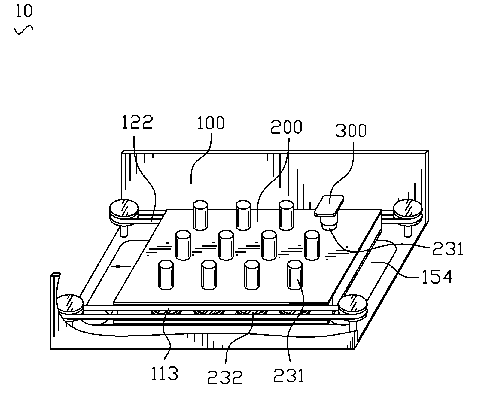
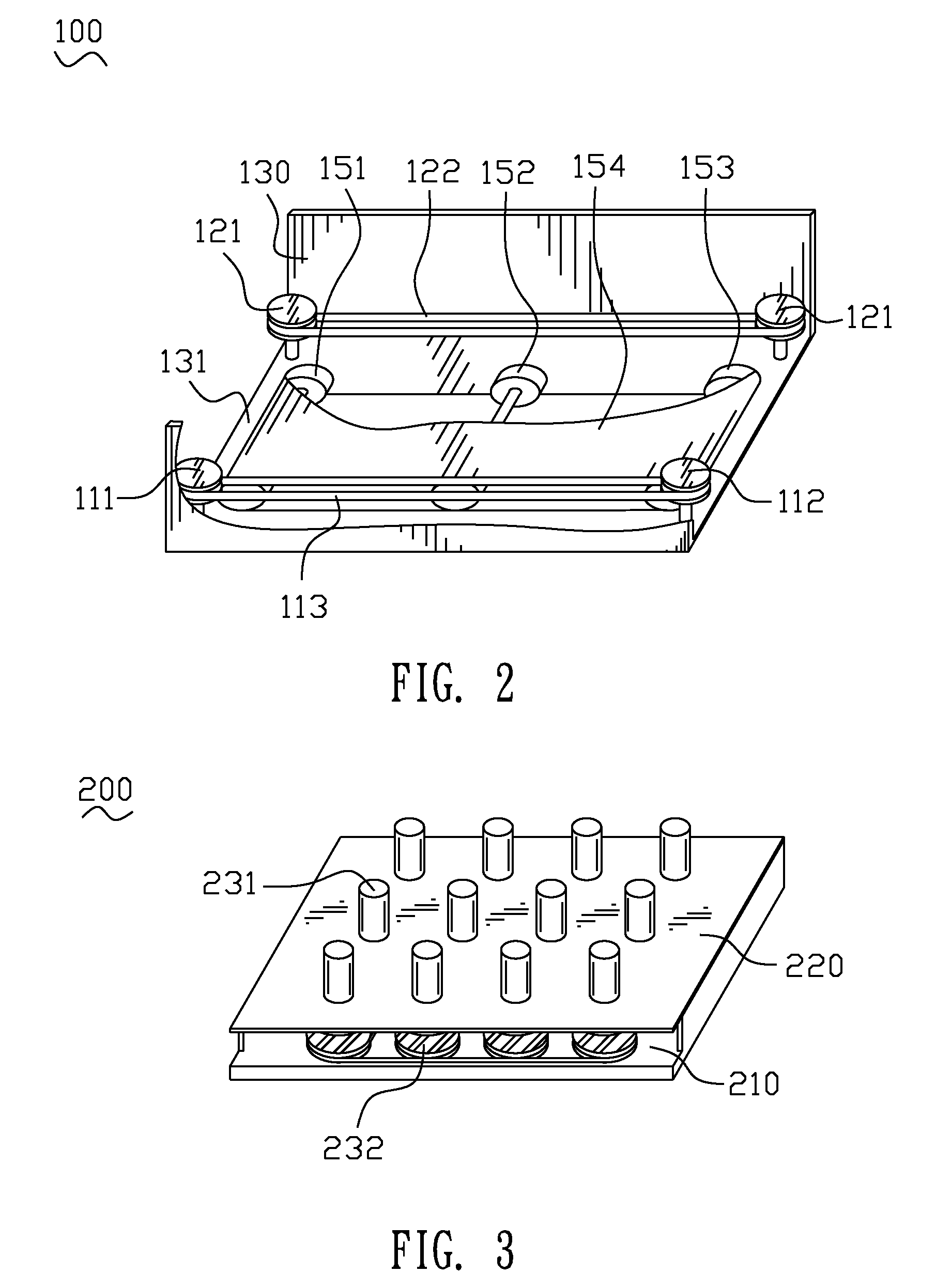
[0016]With reference to FIG. 1, a workpiece-transporting apparatus of in-line sputtering machine 10 includes a plurality of conveyer units 100 (in this embodiment, only one of the conveyer units is shown in FIG. 1) and a carrying salver 200 transported in the conveyer units 100. The conveyer units 100 are serially connected in a line to form a conveyer apparatus.

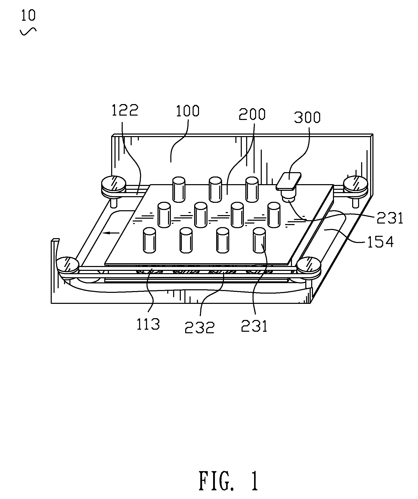
[0017]Please refer to FIG. 2, the conveyer unit 100 includes a holder 130, the holder 130 has a holding base 131 showing a rectangle shape. An impelling wheel 151 is arranged in a left end of the holding base 131. The impelling wheel 151 connects with a motor (not shown). A following wheel 153 is arranged in a right end of the holding base 131. A middle wheel 152 is arranged in the middle of the holding base 131 and located between the impelling wheel 151 and the following wheel 153. The impelling wheel 151, the middle wheel 152 and the following wheel 153 compose a transporting wheel group. A conveyer belt 154 covers around...


PUM

PropertyMeasurementUnit
frictionaaaaaaaaaa
shapeaaaaaaaaaa
sizeaaaaaaaaaa

Abstract

A workpiece-transporting apparatus of in-line sputtering machine includes a conveyer unit and a carrying salver. The conveyer unit has a holder, and a transporting wheel group is arranged in the holder. A conveyer belt covers around the transporting wheel group. A driving wheel group is arranged in one side of the conveyer belt and located in the holder. The driving wheel group connects to a motor and surrounded by a connecting belt. The carrying salver is placed on the conveyer belt of the conveyer unit. The carrying salver has a base, a plurality of supporting shafts are assembled in the base and linked together for being driven together. A workpiece base is arranged on the supporting shafts. At least one of the supporting shafts is surrounded by a supporting wheel. The supporting wheel engages with the connecting belt for being driven by the connecting belt.

Description

BACKGROUND OF THE INVENTION[0001]1. Field of the Invention[0002]This present invention relates to an in-line sputtering machine, and more specifically to a workpiece-transporting apparatus of in-line sputtering machine.[0003]2. The Related Art[0004]When a workpiece is sputtered in an in-line sputtering machine by a sputtering source as traditions, the workpiece is put on a carrying salver for being conveyed in the in-line sputtering machine. The sputtering source can only sputter along a certain direction, an outer surface of the workpiece is not sputtered entirely and uniformly. As the outer surface of the workpiece is not a plate surface, a sputtering film formed in the outer surface of the workpiece by the in-line sputtering machine is not uniform.[0005]Conventionally, in order to sputter the workpiece uniformly, a transporting apparatus is arranged in the in-line sputtering machine, the carrying salver is arranged in the transporting apparatus, and is driven to rotate by a corre...

Claims


Application Information

Patent Timeline
Patent Type & Authority Patents(United States)
IPC IPC(8): B65G17/32
CPCC23C14/505C23C14/56
Inventor LIU, DEAN-KUOLIN, HUNG-HSIN
Owner CHENG UEI PRECISION IND CO LTD
Why Eureka
Try Eureka