Sputtering tool

A technology of sputtering and jigs, which is applied in the field of jigs, can solve the problems of unsatisfactory sputtering, uneven sputtering, and affecting product yield, so as to achieve the effect of ensuring sputtering and improving yield

Inactive Publication Date: 2010-02-10
HONG FU JIN PRECISION IND (SHENZHEN) CO LTD +1
View PDF0 Cites 1 Cited by
  • Summary
  • Abstract
  • Description
  • Claims
  • Application Information

AI Technical Summary

Problems solved by technology

However, since the film material is above the mirror holder 20, when the atomic stream flows from the mirror holder top 21 to the mirror holder bottom 22, it may cause uneven sputtering and the outer side wall 222 of the mirror holder bottom 22 cannot be sputtered.
Affected product yield

Method used


Image

  • Sputtering tool
  • Sputtering tool
  • Sputtering tool

Examples


Embodiment Construction

[0015] The present invention will be described in further detail below in conjunction with the accompanying drawings.

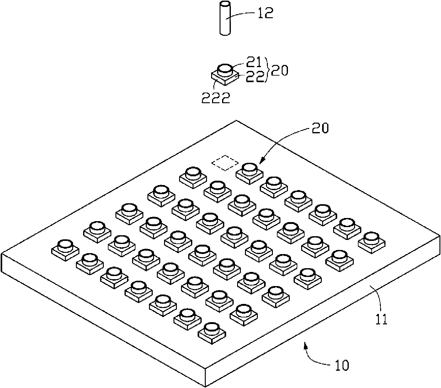
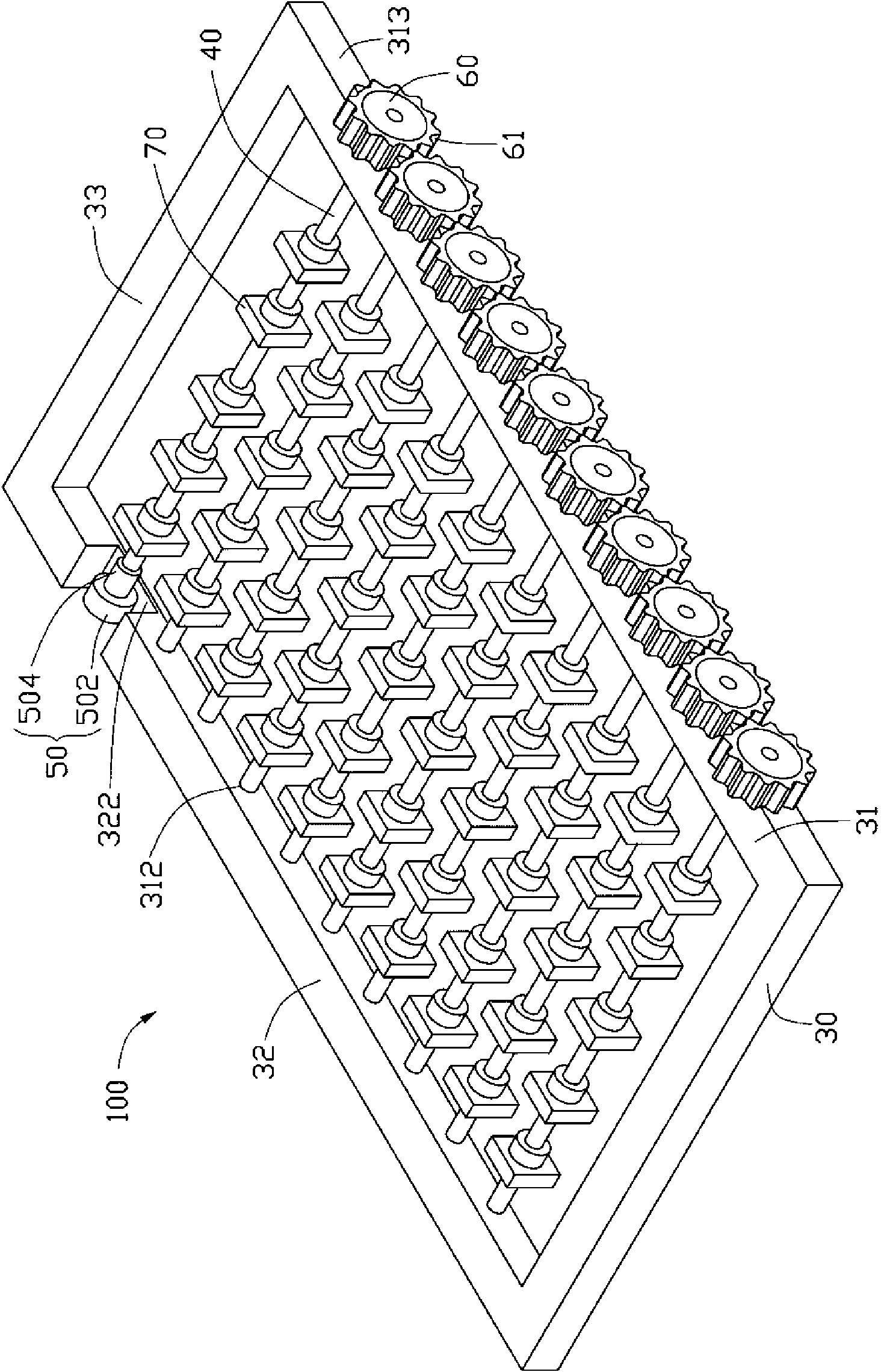
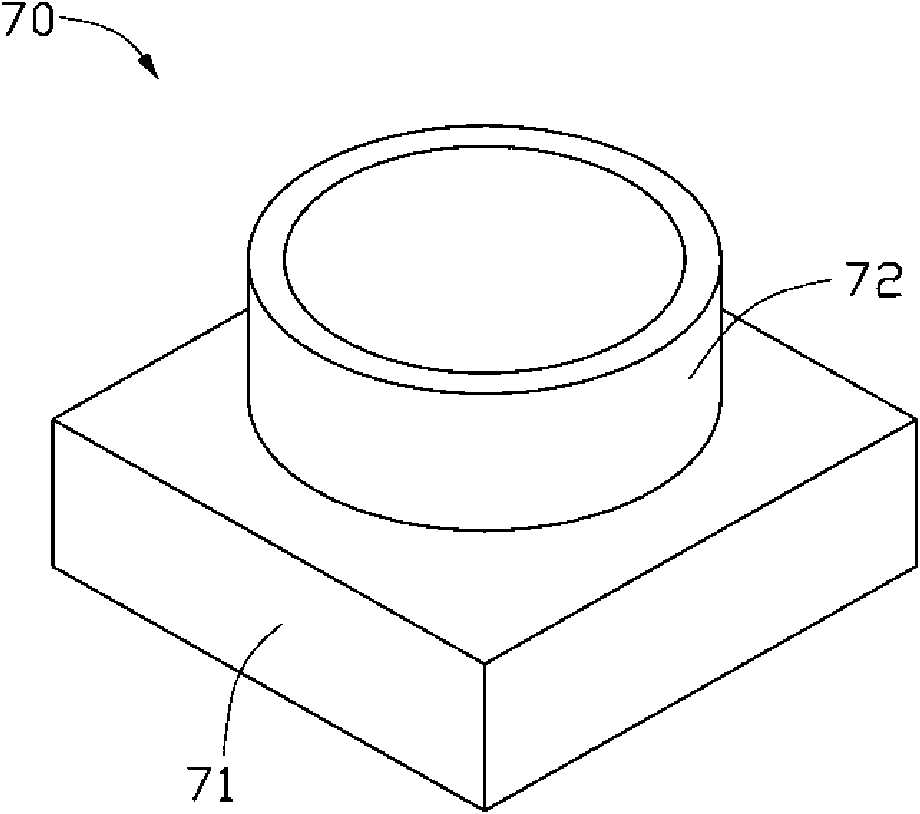
[0016] Please refer to Figure 2 to Figure 4 , is the sputtering fixture 100 of the first embodiment of the present invention, which is used for such as image 3 The shown mirror base 70 to be sputtered is sputtered with an anti-electromagnetic interference film layer. The mirror base 70 generally includes a base 71 and a cylindrical mirror base top 72 extending from the base 71 . The sputtering fixture 100 is used for sputtering the film material on the outer surface of the mirror holder 70 . The sputtering tool 100 includes a bracket 30, at least one rotating rod 40, a driving element 50 and at least two driven elements 60, and the at least two driven elements 60 are respectively arranged on one end of the rotating rod 40, so that The driving member 50 drives one of the rotating rods 40 to rotate with the driven member 60, and the other rotating rods 40 ...


PUM


Abstract

The invention relates to a sputtering tool which comprises a bracket and at least one rotating rod, wherein the bracket comprises a first lateral side and a second lateral side which are opposite arranged, and at least a group of corresponding shaft holes are respectively arranged on the first lateral side and the second lateral side; the rotating rod is arranged in the shaft hole in a penetratingway; the sputtering tool further comprises a driving component and at least two driven components; at least two driven components are respectively on one end of the corresponding rotating rod; the driving component drives one rotating rod and the driven component to rotate; and other rotating rods are driven by the driven components to rotate together, thereby driving a microscope stand to be sputtered on the rotating rod to rotate. The sputtering tool utilizes the matching of the driving component and the driven components to drive the microscope stand to be sputtered to rotate in the bracket, thereby not only ensuring the sputtering evenness, but also improving the sputtering yield ratio simultaneously.

Description

technical field [0001] The invention relates to a jig, in particular to a sputtering jig. Background technique [0002] Sputtering is the use of ions generated by plasma to hit the cathode target, and the atoms in the target are knocked out and deposited on the surface of the substrate to form a film layer. Because sputtering can achieve better deposition efficiency, precise composition control, and lower manufacturing cost, it is widely used in industry. [0003] At present, the application of mobile phone digital camera lenses has become more and more popular, so it is necessary to improve the manufacturing technology of its key components to effectively reduce its manufacturing cost and improve its yield rate. A lens module, one of the key components of a camera lens, usually includes a lens mount, a lens barrel, and elements contained in the lens barrel, such as a spacer, an aperture, and an IR-cut filter. For the design method of the lens holder, please refer to the p...

Claims


Application Information

Patent Timeline
Patent Type & Authority Applications(China)
IPC IPC(8): C23C14/34C23C14/50
Inventor 王仲培
Owner HONG FU JIN PRECISION IND (SHENZHEN) CO LTD
Why Eureka
Try Eureka