Vacuum coating method for outer surface of mobile phone shell

A technology of vacuum coating and mobile phone shell, which is applied in the directions of vacuum evaporation coating, sputtering coating, ion implantation coating, etc., which can solve the problem of uneven sputtering of coating layer thickness and achieve the effect of improving quality

Active Publication Date: 2021-04-16
东莞铱诺科技有限公司
View PDF8 Cites 1 Cited by
  • Summary
  • Abstract
  • Description
  • Claims
  • Application Information

AI Technical Summary

Problems solved by technology

[0004] The purpose of the present invention is to solve the shortcoming of non-uniform coating layer thickness sputtering in the prior art, and propose a vacuum coating method for the outer surface of the mobile phone shell

Method used


Image

  • Vacuum coating method for outer surface of mobile phone shell
  • Vacuum coating method for outer surface of mobile phone shell
  • Vacuum coating method for outer surface of mobile phone shell

Examples


Embodiment 1

[0029] A vacuum coating method for the outer surface of a mobile phone case, comprising the following steps;

[0030] Step 1: The mobile phone case is made of metal material, and the back and edge of the mobile phone case are mirror polished;

[0031] Step 2: Clean and dedust the mobile phone case after step 1, and then dry the mobile phone case after cleaning and dedusting;

[0032] Step 3: Put the mobile phone case that has passed step 2 into the corresponding vacuum coating equipment, and take it out after a certain period of time to complete the coating.

[0033] The coating of the mobile phone shell is completed through polishing, cleaning and dust removal, drying and vacuum coating.

Embodiment 2

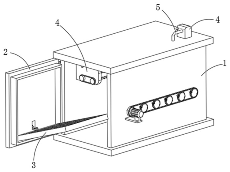
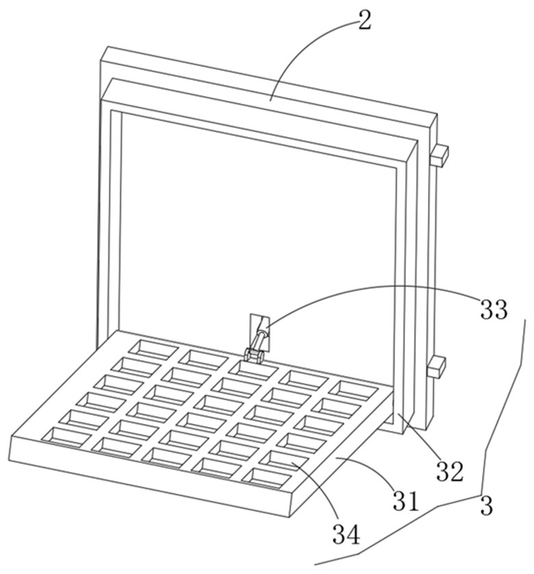
[0035] refer to Figure 1-6 , as another preferred embodiment of the present invention, the difference from Embodiment 1 is that in step 3, the vacuum coating equipment includes a box body 1, the outside of the box body 1 is hinged with a box door 2, and the inside of the box door 2 is installed with Placement mechanism 3, placement mechanism 3 comprises placement plate 31, and the inner side of box door 2 is fixedly installed with the accommodation frame 32 corresponding with placement plate 31, and one end of placement plate 31 is connected with accommodation frame 32 rotations, and the interior rotation installation of accommodation frame 32 There is a telescopic rod 33, the output end of the telescopic rod 33 is hinged with the placement plate 31, and the inner side of the placement plate 31 is provided with a plurality of placement slots 34, and the placement slots 34 are used to place the mobile phone casing;

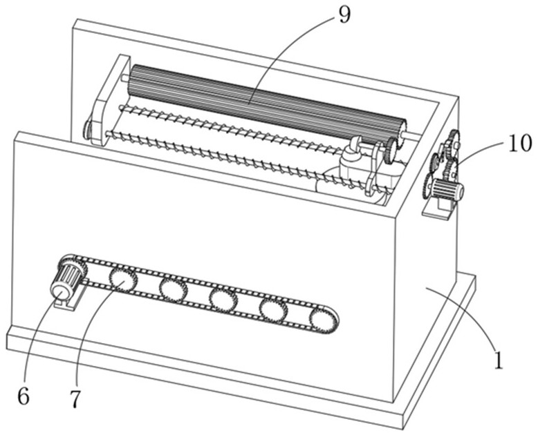
[0036] A coating mechanism 9 is installed in the box body 1,...

Embodiment 3

[0040] refer to Figure 1-6 , as another preferred embodiment of the present invention, the difference from Embodiment 1 or Embodiment 2 is that a drying mechanism 8 is installed on the inside of the box body 1, and the drying mechanism 8 includes an installation box 81, which is fixedly installed on Inside the box body 1, the inside of the installation box 81 is fixedly equipped with a heating pipe 82, and the inside of the installation box 81 is installed with a number of impellers 83, and the outside of the impeller 83 is coaxially fixed with a sprocket 7, and the sprockets 7 pass through The chain transmission connection, the outer side of the box body 1 is fixedly installed with the corresponding second motor 6, the output shaft of the second motor 6 is fixedly connected with the corresponding sprocket 7; the top of the box body 1 is fixedly installed with the corresponding vacuum pump 4, the vacuum pump 4 A conduit 5 is fixedly installed at the input end, and the conduit...


PUM


Abstract

The invention relates to the technical field of mobile phone shell film coating, in particular to a vacuum film coating method for an outer surface of a mobile phone shell, which completes the film coating work of the mobile phone shell through polishing treatment, cleaning and dust removal, drying and vacuum film coating; and meanwhile, a sputtering target can uniformly sputter a coating layer on the mobile phone shell through corresponding vacuum coating equipment, so that the quality of the mobile phone shell is improved.

Description

technical field [0001] The invention relates to the technical field of film coating of mobile phone shells, in particular to a vacuum film coating method for the outer surface of a mobile phone shell. Background technique [0002] At present, with the popularization of electronic communication, mobile phones have been widely used. With the improvement of people's living standards, people pursue the performance requirements of mobile phones on the one hand, and on the other hand, they have higher and higher requirements for the appearance of mobile phones; the mobile phone shell is an important part related to the appearance of mobile phones. The coating quality of the mobile phone case determines the appearance quality of the mobile phone case. At present, sputtering coating equipment is generally used to coat mobile phone casings. Sputtering equipment is designed to coat low-e film, low-e solar film and solar control film on flat architectural glass. The glass plate is con...

Claims


Application Information

Patent Timeline
Patent Type & Authority Applications(China)
IPC IPC(8): C23C14/34C23C14/02C23C14/58
CPCY02A30/00
Inventor 周敬理
Owner 东莞铱诺科技有限公司
Why Eureka
Try Eureka