Method for positioning sub-resolution assist features

a technology of assist features and sub-resolution, applied in the field of photolithography, can solve the problems of reducing circuit performance, limiting wave properties in lithography, and increasing parasitic capacitance, and achieve the effect of increasing performan

Active Publication Date: 2010-04-06
TEXAS INSTR INC
View PDF18 Cites 15 Cited by
  • Summary
  • Abstract
  • Description
  • Claims
  • Application Information

AI Technical Summary

Benefits of technology

This approach allows for improved circuit performance by selectively applying narrower or wider interconnect widths based on route length, reducing overall parasitics and enhancing circuit efficiency.

Problems solved by technology

In general, these wave properties are seen as being a limiting factor in lithography.
Today, interconnect pattering has become the bottleneck in achieving continued enhanced circuit performance.
In sub-100 nm technologies, this often results in interconnect lines being printed much wider than drawn to overcome photolithographic issues, which can result in increased parasitic capacitance and hence reduced circuit performance.

Method used


Image

  • Method for positioning sub-resolution assist features
  • Method for positioning sub-resolution assist features
  • Method for positioning sub-resolution assist features

Examples


Embodiment Construction

[0026]Reference will now be made in detail to various exemplary embodiments of the present application, examples of which are illustrated in the accompanying drawings. Wherever possible, the same reference numbers will be used throughout the drawings to refer to the same or like parts.

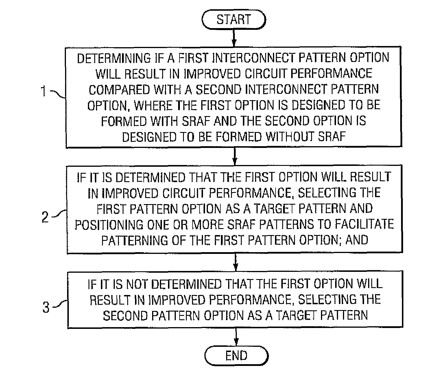
[0027]FIG. 1 illustrates a flow chart of a process for selectively positioning one or more sub-resolution assist features (SRAFs) when forming an interconnect pattern for a photomask, according to one embodiment of the present application. The photomask may be used for making any type of photomask known in the art, such as, for example, binary photomasks, phase shift photomasks, attenuating photomasks, as well as others.

[0028]The method of FIG. 1 can be performed as part of a more general method for forming a photomask pattern that can include various other additional processes that are not illustrated. Methods for forming photomask patterns are well known in the art, and can involve, for example, gene...


PUM


Abstract

The present application is directed to a method of selectively positioning sub-resolution assist features (SRAF) in a photomask pattern for an interconnect. The method comprises determining if a first interconnect pattern option will result in improved circuit performance compared with a second interconnect pattern option, where the first option is designed to be formed with SRAF and the second option is designed to be formed without SRAF. If it is determined that the first option will result in improved circuit performance, the first pattern option is selected as a target pattern and one or more SRAF patterns are positioned to facilitate patterning of the first pattern option. If it is not determined that the first option will result in improved performance, the second pattern option is selected as a target pattern.

Description

DESCRIPTION OF THE DISCLOSURE[0001]1. Field of the Disclosure[0002]The present application relates generally to the field of photolithography, and more specifically to a method for selectively positioning sub-resolution assist features of a photomask pattern.[0003]2. Background of the Disclosure[0004]Conventional optical projection lithography has been the standard silicon patterning technology for the past 20 years. It is an economical process due to its inherently high throughput, thereby providing a desirable low cost per part or die produced. A considerable infrastructure (including steppers, photomasks, resists, metrology, etc.) has been built up around this technology.[0005]In optical projection lithography, a mask, or “reticle”, is employed that includes a mask pattern for defining device features to be patterned, often formed of, for example, opaque chrome on a transparent glass substrate. A stepper projects light through the mask and images the mask pattern, often with a 4×...

Claims


Application Information

Patent Timeline
Patent Type & AuthorityPatents(United States)
IPC IPC(8): G06F17/50
CPCG03F1/144G03F1/36
InventorSAVITHRI, NAGARAJMASON, MARK E.MCKEE, WILLIAM R.
OwnerTEXAS INSTR INC