Air compressor and method for controlling the same

a technology of air compressor and air compressor, which is applied in the direction of positive displacement liquid engine, pump control, motor parameter, etc., can solve the problems of not always in a sufficient electric power environment for air compressor use, considerable noise is produced when the motor is rotating, and the speed of rotation can be controlled more easily, so as to improve the efficiency of compressed air generation. , the effect of improving the efficiency of air compressor

Active Publication Date: 2010-04-27
KOKI HLDG CO LTD
View PDF20 Cites 44 Cited by
  • Summary
  • Abstract
  • Description
  • Claims
  • Application Information

AI Technical Summary

Benefits of technology

[0015]When the rotational speed of the motor is controlled multistageously in this manner according to the tank pressure, the state of load can be predicted so that compressed air can be generated efficiently. Shortage of power can be prevented even in the case where a large amount of air is used. The rotational speed can be reduced to achieve a low-noise operation when a small amount of air is used.
[0017]In this configuration, the amount of air to be used can be predicted more delicately, so that the power-improving and noise-reducing effect can be improved more greatly.
[0019]In this configuration, the rotational speed can be controlled more easily.
[0020]In the invention, the rotational speed of the motor may be set multistageously to have a plurality of values such as 0, N, 2 N, 3N, . . . , and nN (in which n is an arbitrary number), so that one of the values is selected by the control circuit portion to thereby control the motor. When the rotational speed is controlled multistageously in this manner, efficiency in generation of compressed air can be improved compared with the related-art on / off control.
[0025]The invention may provide an air compressor including a tank portion for reserving compressed air used in a pneumatic tool, a compressed air generation portion for generating compressed air and supplying the compressed air to the tank portion, a drive portion having a motor for driving the compressed air generation portion, and a control circuit portion for controlling the drive portion, wherein: the air compressor further includes a pressure sensor for detecting pressure of the compressed air reserved in the tank portion; and the rate ΔP1 / ΔT1 of change ΔP1 in internal pressure of the tank portion to a relatively short time ΔT1 and the rate ΔP2 / ΔT2 of change ΔP2 in internal pressure of the tank portion to a time ΔT2 longer than the time ΔT1 are calculated on the basis of detection signals output from the pressure sensor so that the rotational speed of the motor multistageously is controlled on the basis of at least one of the two pressure change rates.

Problems solved by technology

Because the air compressor has a mechanism for converting the rotation of the motor into the reciprocating motion of the piston in the cylinder, it is unavoidable that considerable noise is produced when the motor is rotating.
Furthermore, because the pneumatic tool such as a nailing machine using compressed air generated by the air compressor produces operating noise when the pneumatic tool is operating, the operating noise is combined with the air compressor's own noise so that considerable noise is produced around the building site.
The place where the air compressor is used is not always in a sufficient electric power environment.
The air compressor may be rather used in such an environment that it is impossible to keep a sufficiently high voltage because a long cord needs to be used for providing a power-supply voltage from another place, or in such an environment that a great deal of compressed air must be consumed because a large number of pneumatic tools need to be used simultaneously.
For this reason, it may be impossible to produce a high-power output from the air compressor.
If, for example, a nailing machine is used in the condition that the output is insufficient, nailing is performed shallowly and there arises a problem that it is impossible to nail a workpiece sufficiently.
It is unavoidable that the air leaks little by little when there is no tool used.
There is another problem that lowering of efficiency may be brought about in accordance with how to use the air compressor.
There is a problem that the life of the air compressor used for pneumatic tool is shorter than the life of a compressor used for refrigerator, air-conditioner, etc.
Although it is unavoidable in one aspect that the air compressor is short-lived because the air compressor is used in a harsh environment, suppression of change in load to the utmost or suppression of generation of wasteful compressed air to the utmost is required for attaining prolongation of the life.
It is unavoidable that the temperature of the air compressor becomes considerably high because of the reciprocating motion of the piston in the cylinder and the electric current flowing in the motor for driving the piston.
The high temperature of the air compressor, however, causes increase in loss and disturbance of efficiency.

Method used


Image

  • Air compressor and method for controlling the same
  • Air compressor and method for controlling the same
  • Air compressor and method for controlling the same

Examples


Embodiment Construction

The First Preferred Embodiment

[0047]A first preferred embodiment of the invention will be described below in detail.

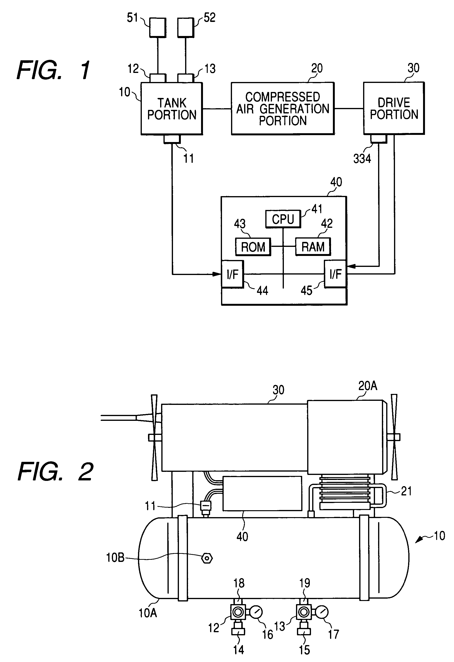
[0048]FIG. 1 is a conceptual view of an air compressor according to the invention. As shown in FIG. 1, the air compressor includes a tank portion 10 for reserving compressed air, a compressed air generation portion 20 for generating compressed air, a drive portion 30 for driving the compressed air generation portion 20, and a control circuit portion 40 for controlling the drive portion 30.

(1) Tank Portion 10

[0049]As shown in FIG. 2, the tank portion 10 includes an air tank 10A for reserving high-pressure compressed air. For example, 20 kg / cm2 to 30 kg / cm2 of high-pressure compressed air are supplied to the air tank 10A through a pipe 21 connected to an outlet port of a compressor portion 20A.

[0050]The air tank 10A is generally provided with a plurality of compressed air output ports 18 and 19. In this embodiment, there is shown an example in which an output port 18 for...


PUM


Abstract

An air compressor includes: a tank portion for reserving compressed air used in a pneumatic tool; a compressed air generation portion for generating compressed air and supplying the compressed air to the tank portion; a drive portion including a motor for driving the compressed air generation portion; a control circuit portion for controlling the drive portion; and a pressure sensor for detecting pressure of the compressed air reserved in the tank portion. The control circuit portion includes a unit for controlling the rotational speed of the motor multistageously on the basis of a detection signal output from the pressure sensor.

Description

BACKGROUND OF THE INVENTION[0001]1. Field of the Invention[0002]The present invention relates to an air compressor for generating compressed air used in a pneumatic tool such as a pneumatic nailing machine, and a method for controlling the air compressor.[0003]2. Background Art[0004]Generally, an air compressor used for pneumatic tool is configured so that a crankshaft of a compressor body is driven to rotate by a motor to reciprocate a piston in a cylinder in accordance with the rotation of the crankshaft to thereby compress air sucked in from an inlet valve. The compressed air generated in the compressor body is discharged from an outlet valve to an air tank through a pipe and reserved in the tank. The pneumatic tool does its work such as nailing by using the compressed air reserved in the tank.[0005]The air compressor is often carried to a building site and used outdoors or is often used in a densely populated place. For this reason, the air compressor needs to be improved from v...

Claims


Application Information

Patent Timeline
Patent Type & Authority Patents(United States)
IPC IPC(8): F04B49/06F04B41/02
CPCF04B41/02F04B49/065F04B2203/0209
Inventor IIMURA, YOSHIOORIKASA, HIROAKISUNAOSHI, MITSUHIROUCHIDA, TOSHIAKISEGAWA, KAZUHIRO
Owner KOKI HLDG CO LTD
Why Eureka
Try Eureka