Ignition switch device

a switch and ignition technology, applied in the field of ignition switch devices, can solve the problems of inability to describe prior art documents, easy scratches on the surface, and impaired design quality of appearance, so as to keep the surface of the case from being scratched and maintain the effect of design quality

Active Publication Date: 2010-05-04
ASAHI DENSO KABUSHIKI KAISHA +1
View PDF32 Cites 3 Cited by
  • Summary
  • Abstract
  • Description
  • Claims
  • Application Information

AI Technical Summary

Benefits of technology

[0009]One or more embodiments of the invention provide an ignition switch device which allows smooth rotation of a shutter to be performed, and which can keep the surface of a case from being scratched, thereby maintaining design quality.
[0014]According to the first aspect, the ignition switch device provided with the protruding portion which is formed within the range of rotation of the shutter while protruding from the surface of the case and whose protruding end contacts a rear surface of the shutter while the shutter rotates. Thus, smooth rotation of the shutter can be performed, and the surface of the case can be kept from being scratched, thereby maintaining design quality. That is, during the rotation of the shutter, the rear surface of the shutter will contact only the protruding end of the protruding portion. As a result, a place to which any scratches are given will be limited, and the scratches will not be conspicuous. Therefore, the design quality of the surface of the case can be maintained.
[0015]Further, according to the second aspect, the protruding portion is formed such that its protruding end is sharpened. Thus, during the rotation of the shutter, the rear surface of the shutter will contact only the sharpened protruding end of the protruding portion. As a result, a place where any scratches are given will be limited, and will not be conspicuous. Therefore, the design quality of the surface of the case can be maintained more reliably.
[0016]According to the third aspect, the convex shape is formed along the contour edge of the rear surface of the shutter. Thus, while the shutter rotates, only the convex shape of the shutter and the protruding end of the protruding portion will contact each other. As a result, the contact area therebetween can be reduced to further keep the rear surface of the case from being scratched. Further, when the rear surface of the shutter freezes during a winter season, only the convex shape of the shutter and the protruding end of the protruding portion contact each other, the contact area therebetween is small and the frozen place is extremely limited. Thus, the shutter can be rotated with slight force.
[0017]According to the fourth aspect, the protruding portion is formed so as to extend in an arc along the locus of rotation of the shutter. Thus, a three-dimensional design can be provided so as to indicate the rotation direction of the shutter, and the rotational operation of the shutter can be made smoother.

Problems solved by technology

In addition, since such prior art is not related to inventions well-known in literatures, there is no information on prior art documents to be described.
However, in a case where the shutter is simply provided in the above conventional ignition switch device, there is a problem in that, when the shutter is rotated on the surface of the case, scratches are apt to be given to the surface, and the design quality of appearance is impaired.
In this case, however, it is necessary to support the shutter rotatably in a state where the shutter is floated from the surface of the case, and there is a possibility that smooth rotation of the shutter may not be performed due to generation of a gutter or the like.
Accordingly, it is necessary to make the rear surface of the shutter contact the surface of the case, and a problem that scratches are given to the surface of the case occurs.

Method used


Image

  • Ignition switch device
  • Ignition switch device
  • Ignition switch device

Examples


Embodiment Construction

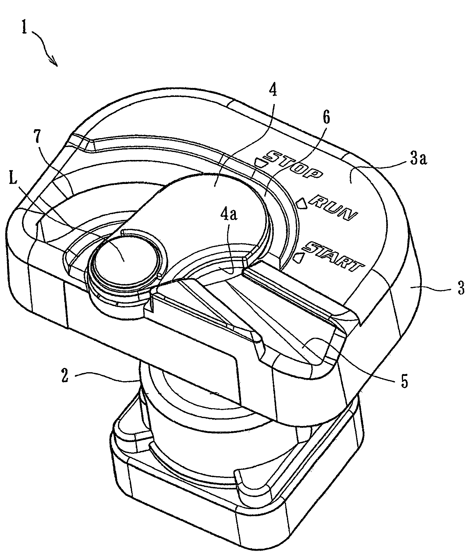
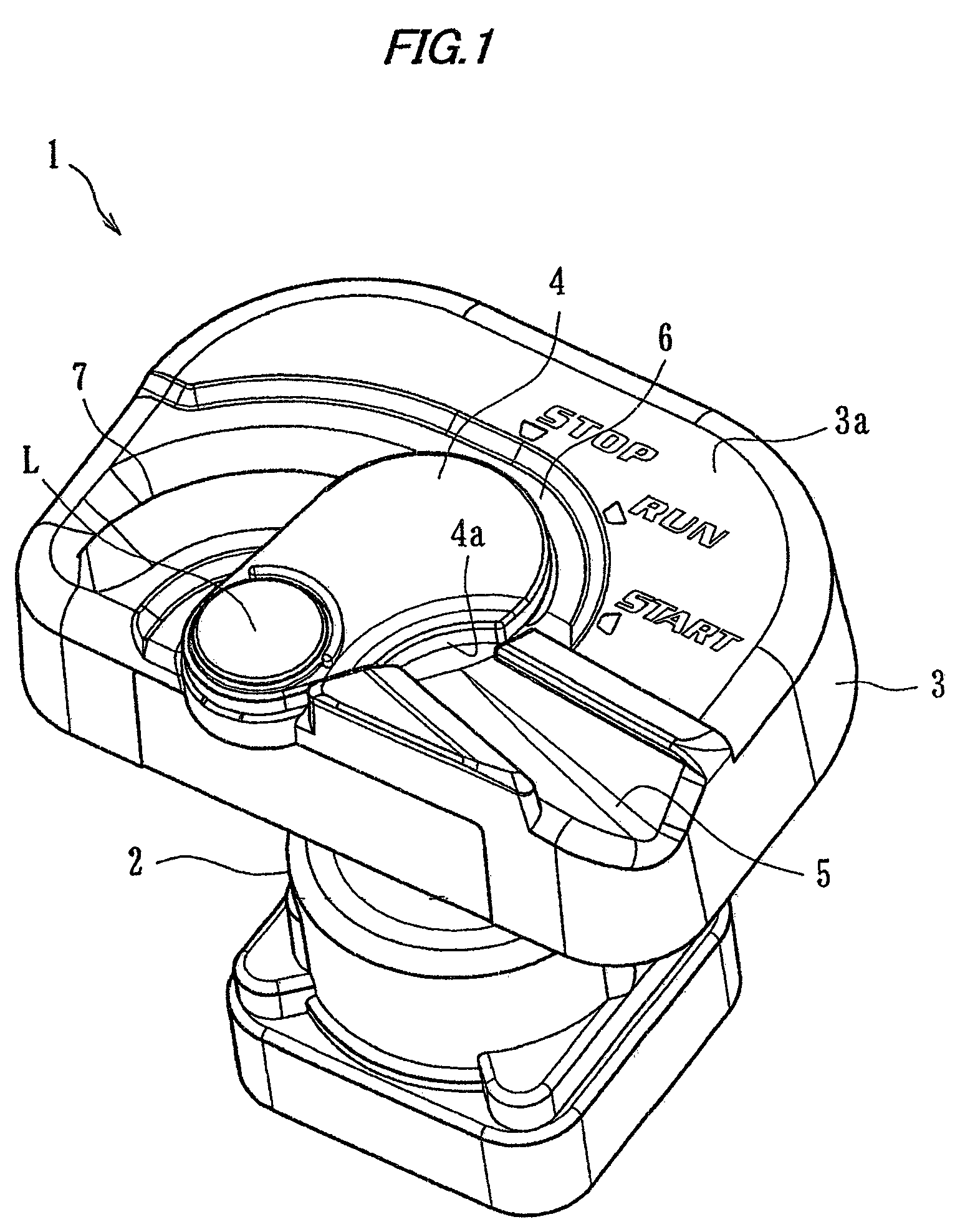
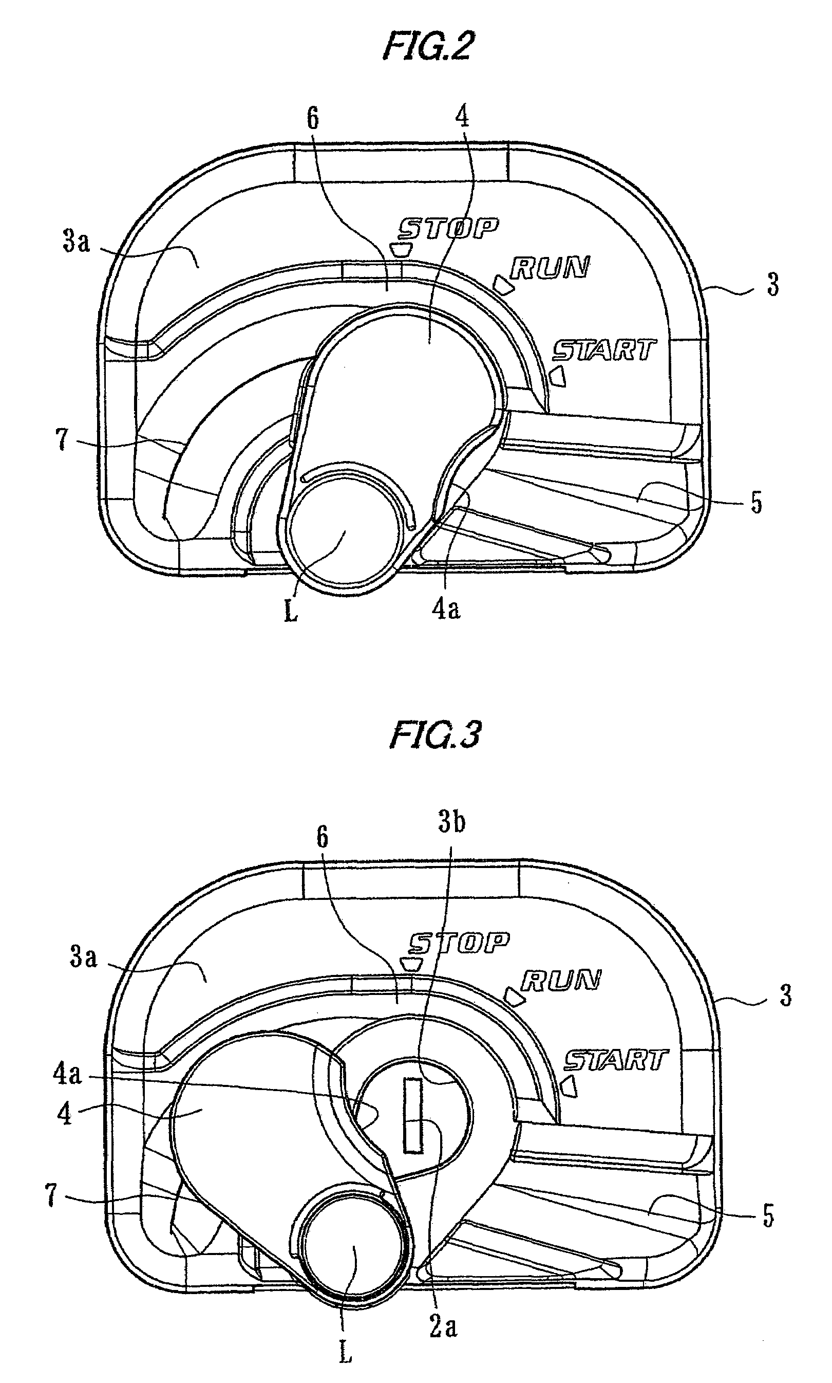
[0041]An exemplary embodiment of the invention will be specifically explained with reference to the drawings. An ignition switch device related to the present embodiment is disposed in driver's seats of industrial machines (construction machines), such as bulldozers, power shovels, or crane vehicles to be used in worksites of engineering works or construction. As shown in FIG. 1, the ignition switch device is mainly composed of a switching means 2, a case 3, a shutter 4, a main guide shape 5, an auxiliary guide shape 6, and a protruding portion 7.

[0042]The switching means 2 includes a key hole 2a (refer to FIG. 3) which allows a regular ignition key K to be inserted thereinto, and can be operated to rotate in a predetermined direction with the ignition key K inserted thereinto to thereby start and stop the engine of an industrial machine. Specifically, the switching means 2 constitutes a cylinder lock in which a plurality of tumblers are provided within the key hole 2a, or a versati...


PUM


Abstract

An ignition switch device is provided with a switching device 2 having a key hole 2a, and capable of being rotationally operated in a predetermined direction with an ignition key K inserted to start and stop the engine of an industrial machine, a case 3 covering the switching device 2 and formed with an insertion hole 3b allowing the key hole 2a to face the outside, a shutter 4 rotatable between a closed position where the insertion hole 3b of the case 3 is closed, and an open position where the insertion hole 3b is opened to allow the key hole 2a to face outside, and a protruding portion 7 formed within the range of rotation of the shutter 4 while protruding from the surface 3a of the case 3 and whose protruding end contacts the rear surface 4b of the shutter 4 while the shutter 4 rotates.

Description

[0001]This application claims foreign priority from Japanese Patent Application No. 2007-140471 filed on May 28, 2007, the entire contents of which are hereby incorporated by reference.BACKGROUND OF THE INVENTION[0002]1. Field of the Invention[0003]The present invention relates to an ignition switch device which is disposed in a driver's seat of an industrial machine to start and stop an engine of the industrial machine.[0004]2. Background Art[0005]An industrial machine, for example, a construction machine is used in a worksite of engineering works and construction, and includes bulldozers, power shovels, and crane vehicles. An ignition switch device for starting and stopping an engine of the industrial machine is disposed in the driver's seat of such an industrial machine. By rotationally operating an ignition key while inserting the key into a key hole of such an ignition switch device, the engine is started and stopped.[0006]The industrial machine is typically used in the open ai...

Claims


Application Information

Patent Timeline
Patent Type & Authority Patents(United States)
IPC IPC(8): E05B17/18E02F9/00E05B83/00
CPCB60R25/04E05B17/185E05B17/002B60R25/2063Y10S70/30Y10T70/5956Y10T70/7955Y10T70/8649F02N11/00F02N15/00
Inventor TSUCHIKIRI, AKIHIKOSAKAI, TAKEHIROUEDA, MASAAKIMIURA, KEISUKEKAWANAMI, HIROSHI
Owner ASAHI DENSO KABUSHIKI KAISHA
Why Eureka
Try Eureka