Display device

a display device and display technology, applied in the field of display devices, can solve the problems of not achieving marked improvement in decorative effect, inability to thicken the character plate, and inability so as to achieve satisfactory decorative effect, reduce the thickness of the display device, and achieve satisfactory decorative effect

Inactive Publication Date: 2010-07-13
TOYODA GOSEI CO LTD
View PDF12 Cites 25 Cited by
  • Summary
  • Abstract
  • Description
  • Claims
  • Application Information

AI Technical Summary

Benefits of technology

[0013]According to the display device of this arrangement, luminous characters are projected directly or are reflected onto the half mirror layer, and a mirror image is generated on the mirror surface. This mirror image is reflected by the half mirror layer, and a new mirror image is generated. Since the generation and reflection of the mirror image is repeated, from the front to the rear, multiple contiguous luminous images are observed via the half mirror layer. As a result, a display form can be obtained that provides a stereoscopic or depth impression and a satisfactory decorative effect. Therefore, spatial effects can also be produced. Thus, when this display is decoratively employed on the ceiling, for example, inside a vehicle or a building, and spatial depth effect can be provided, or a sense of spaciousness can be produced. Furthermore, with this arrangement, not only can satisfactory decorative effects can be provided, but also the thickness of a display device can be reduced, so that the design of the device can also be improved.

Problems solved by technology

However, since the characters are bright only in the plane, the decorative effect obtained is not fully satisfactory, and an increased sense of luxury is desirable.
Furthermore, an attempt to provide a more luxurious luminous image by increasing the thickness of the character plate serves only to improve the stereoscopic effect; no marked improvement in the decorative effect is acquired when the means used to achieve this objective is a mere increase in the thickness of the character plate.
In addition, since the thickness of the character plate directly affects the thickness of the entire device, and because design requirements impose limits on the thickness of the device, thickening the character plate is not a viable solution.

Method used


Image

  • Display device
  • Display device
  • Display device

Examples


first embodiment

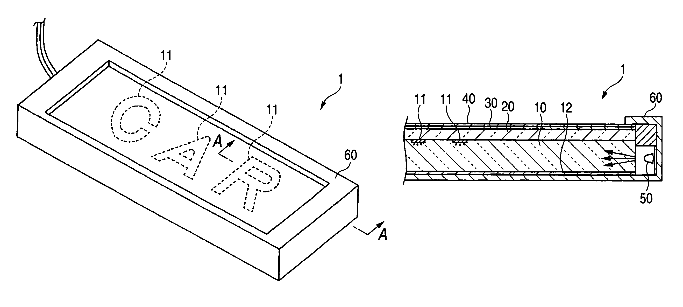
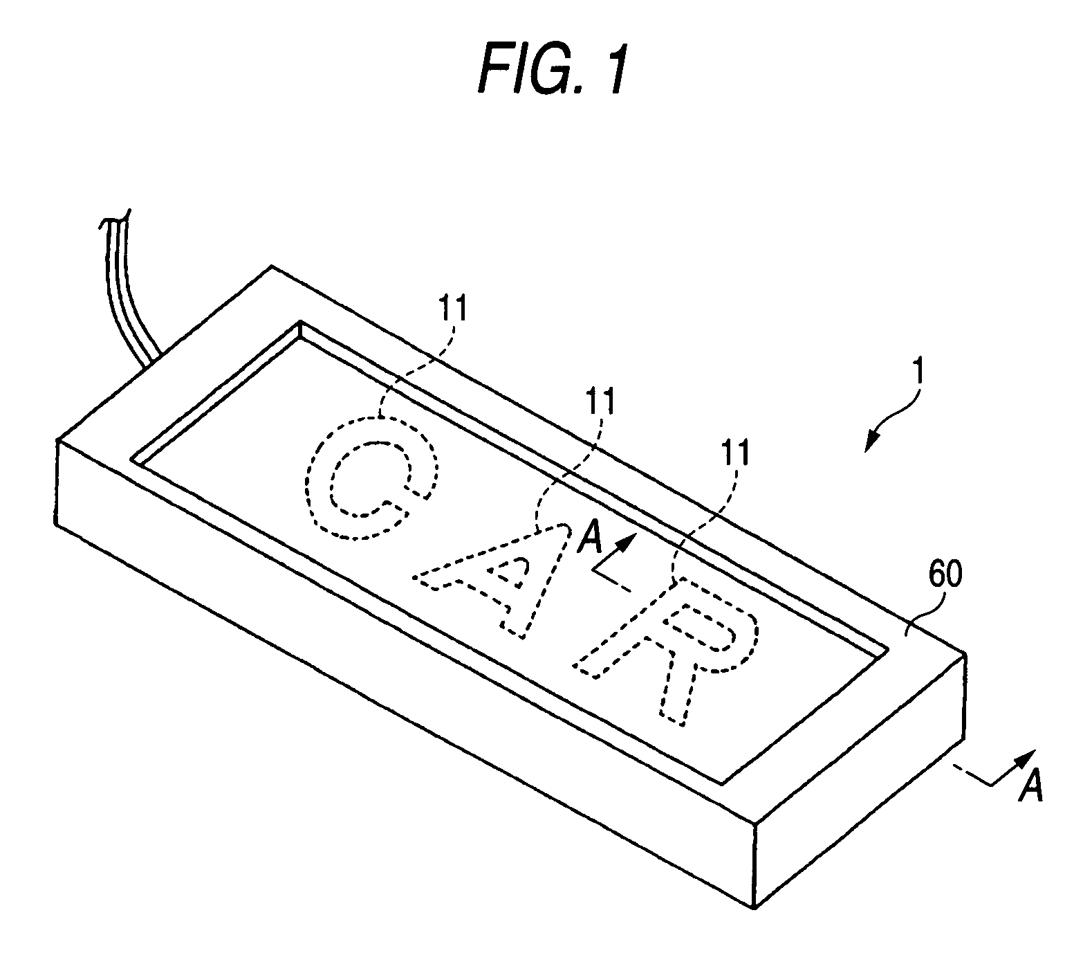
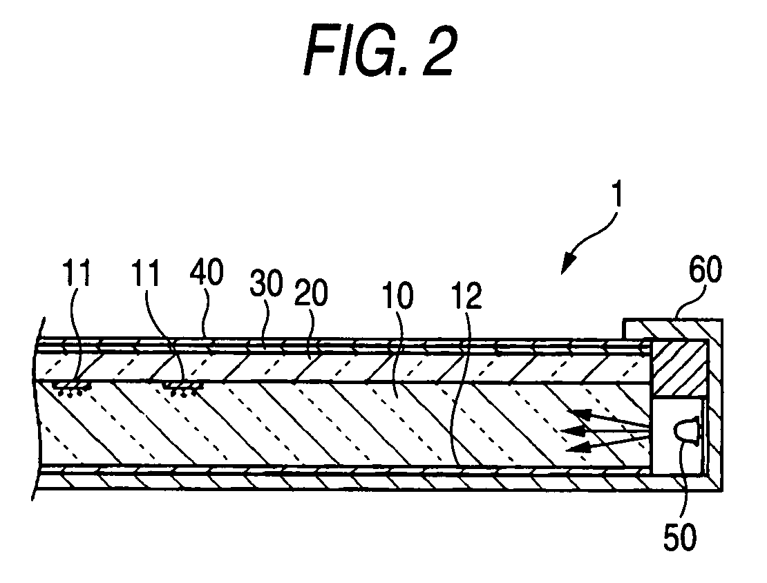
[0041]A display device 1 according to the embodiment of the present invention is shown in FIGS. 1 and 2. FIG. 1 is a perspective view of the display device 1, and FIG. 2 is a cross sectional view of this device taken along a line A-A in FIG. 1. The structure of the display device 1 and a display style provided by the display device 1 will now be described while referring to FIGS. 1 and 2. It should be noted that the display device 1 is employed for the decoration of a scuff plate for an automobile.

[0042]In the display device 1, a first light guidance member 10, a second light guidance member 20, a half mirror film 30 and a protective plate 40 are laminated, in this order, toward the observation face side (above in the figure), and this laminated structure is stored in a cover 60. The individual members, such as the first light guidance member 10, of the structure are rectangular members having substantially the same shape in plan view. The first light guidance member 10 is made of a...

second embodiment

[0050]Another embodiment of the present invention is shown in FIGS. 5 and 6. FIG. 5 is a perspective view of a display device 2 according to the second embodiment, and FIG. 6 is a cross sectional view of the display device 2 taken along a line B-B in FIG. 5. The same reference numerals as used in the first embodiment are provided for identical or corresponding members, and for them, no further explanation will be given.

[0051]For the display device 2, an EL element 70 is employed for luminously displaying characters. The EL element 70 has a structure wherein a rear electrode layer, a dielectric layer, a light emitting layer and a transparent electrode layer (ITO) are laminated in order. Further, a protective layer made of a translucent film is deposited under the rear electrode layer and on the transparent electrode layer. As shown in FIG. 6, the EL element 70 has a shape, in plan view, that enables the surface emission of desired characters (CAR in this embodiment). The EL element 7...


PUM


Abstract

The objective of the present invention is to provide a display device that presents great decorative effects.For a display device that provides a luminous display consisting of characters, numbers, symbols or figures, or arbitrary combinations of them, having a desired form, a half mirror layer is formed above a mirror surface, through a translucent layer, and a desired form is luminously displayed at a location between the mirror surface and the half mirror layer and at a distance from the mirror surface.

Description

BACKGROUND OF THE INVENTION[0001]1. Field of the Invention[0002]The present invention relates to a display device for luminously displaying a desired form, such as a character or a number. The display device of the present invention is used as a decorative item for a vehicle, such as a scuff plate for an automobile or a vehicle interior ceiling ornament, and as a decorative mount for a name plate on a house exterior or as a ceiling ornament inside a house or a building.[0003]2. Description of the Related Art[0004]An automobile scuff plate device that luminously displays characters and provides a decorative effect has been put to practical use. An example of a scuff plate device 100, of a conventional light transmission type, is shown in FIG. 7. For the scuff plate device 100, a character plate 101 (e.g., an aluminum plate), in which characters having a desired form have been stamped out, is laminated on a rectangular light guidance plate 102, to which a white backing material has be...

Claims


Application Information

Patent Timeline
Patent Type & Authority Patents(United States)
IPC IPC(8): G09F13/18
CPCG09F13/22
Inventor MISAWA, AKIHIROTAKEDA, KAZUOOBA, TATSUYA
Owner TOYODA GOSEI CO LTD
Why Eureka
Try Eureka