Paint protection apparatus

a protection apparatus and paint technology, applied in metal working apparatus, thin material processing, coatings, etc., can solve the problems of limited coverage area, increased inconvenience for painters, and inability to prevent paint from dripping, so as to effectively restrict the lateral movement of the housing and the blade during cutting procedures. , the effect of detachabl

Inactive Publication Date: 2010-07-13
NOBLE JAMES
View PDF6 Cites 6 Cited by
  • Summary
  • Abstract
  • Description
  • Claims
  • Application Information

AI Technical Summary

Benefits of technology

[0015]The separating mechanism includes a cutting implement provided with a blade formed at a distal tip thereof. Such a cutting implement includes a housing directly coupled to the blade, and has a bore passing therethrough. A central region (herein described below) is linearly seated through the bore such that the housing is freely adapted along the longitudinal length of the central region. Such a blade is orthogonally registered and extends downwardly from the central region of the holding implement (herein described below) such that the unwound portion effectively engages the blade when the body is flexed upwardly and towards the holding implement. The blade traverses across at least one of the perforations during cutting procedures. The blade is vertically adjustable along a front face of the housing, and is advantageously detachable from the housing while the housing remains anchored to the central region.
[0016]The separating mechanism further includes a plurality of stop members in frictional communication with the central region. Such stop members are advantageously spaced on opposite sides of the housing and the blade respectively, and further are linearly positional along the central region for effectively restricting lateral movement of the housing and the blade during cutting procedures respectively.
[0017]The apparatus further includes a mechanism for unwinding and dispensing the body so that the unwound portion is evenly pulled away from the tubular configuration while one user hand remains advantageously spaced from the unwinding and dispensing mechanism during operating conditions. Such an unwinding and dispensing mechanism preferably includes a holding implement that has axially offset U-shaped end portions facing inwardly toward each other. Each of such U-shaped end portions is removably seated within axially opposed ends of the body while the body is adapted at the tubular configuration such that the body is advantageously journaled about the U-shaped end portions and freely rotatable thereabout. Such a holding implement further includes a telescopic central region monolithically formed with the U-shaped end portions in such a manner that a longitudinal length of the holding implement is conveniently adaptable to alternate lengths after the selected area of the unwound portion of the body is detached from the body.

Problems solved by technology

These protective methods quite often did not prevent paint from dripping down the wall to the juncture where the wall meets the floor since the drop cloth or other type of paint protection device does not adequately seal the wall or baseboard thereby preventing paint from falling on the edges between the wall and the floor or floor coverings.
Unfortunately, this prior art example requires a user to hold the apparatus with one hand while painting a surface with the other hand, thus increasing inconvenience for the painter.
Such an apparatus also has a limited coverage area, and does not effectively seal the juncture of the apparatus and the surface to be protected.
Unfortunately, this prior art example requires the use of a liquid compound which may be difficult to apply and requires a drying time, which may inconveniently delay a painter in accomplishing his task.

Method used


Image

  • Paint protection apparatus
  • Paint protection apparatus
  • Paint protection apparatus

Examples


Embodiment Construction

[0028]The present invention will now be described more fully hereinafter with reference to the accompanying drawings, in which a preferred embodiment of the invention is shown. This invention may, however, be embodied in many different forms and should not be construed as limited to the embodiment set forth herein. Rather, this embodiment is provided so that this application will be thorough and complete, and will fully convey the true scope of the invention to those skilled in the art. Like numbers refer to like elements throughout the figures.

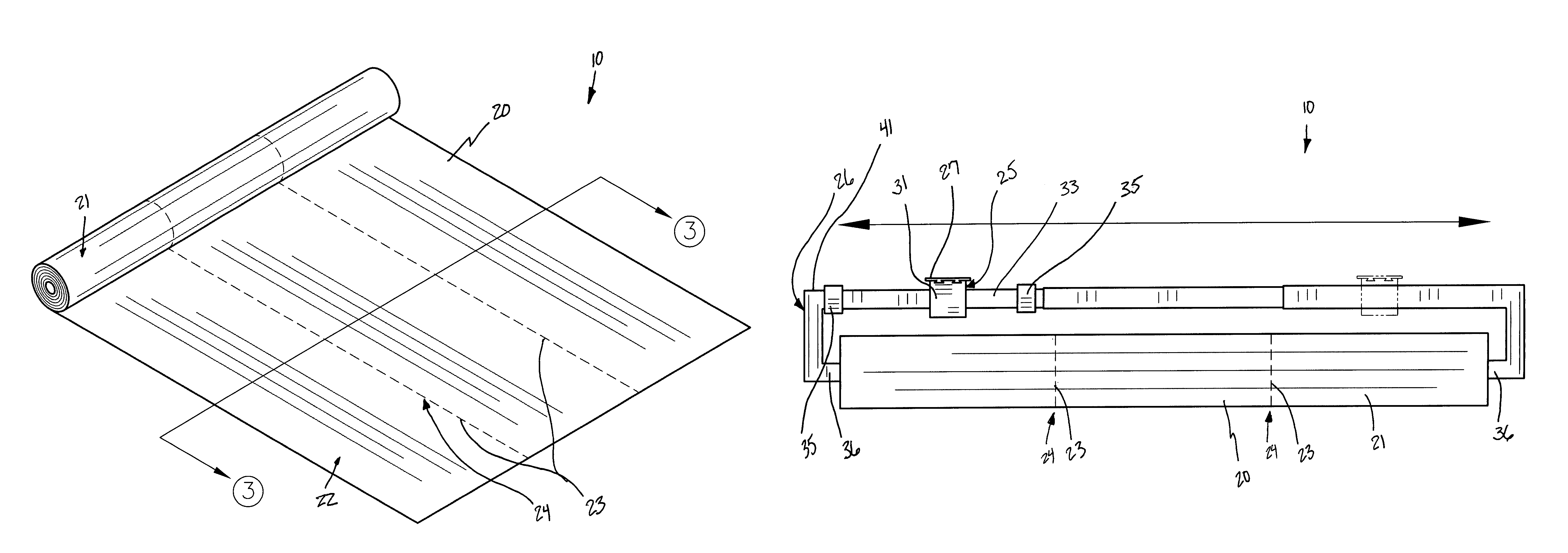
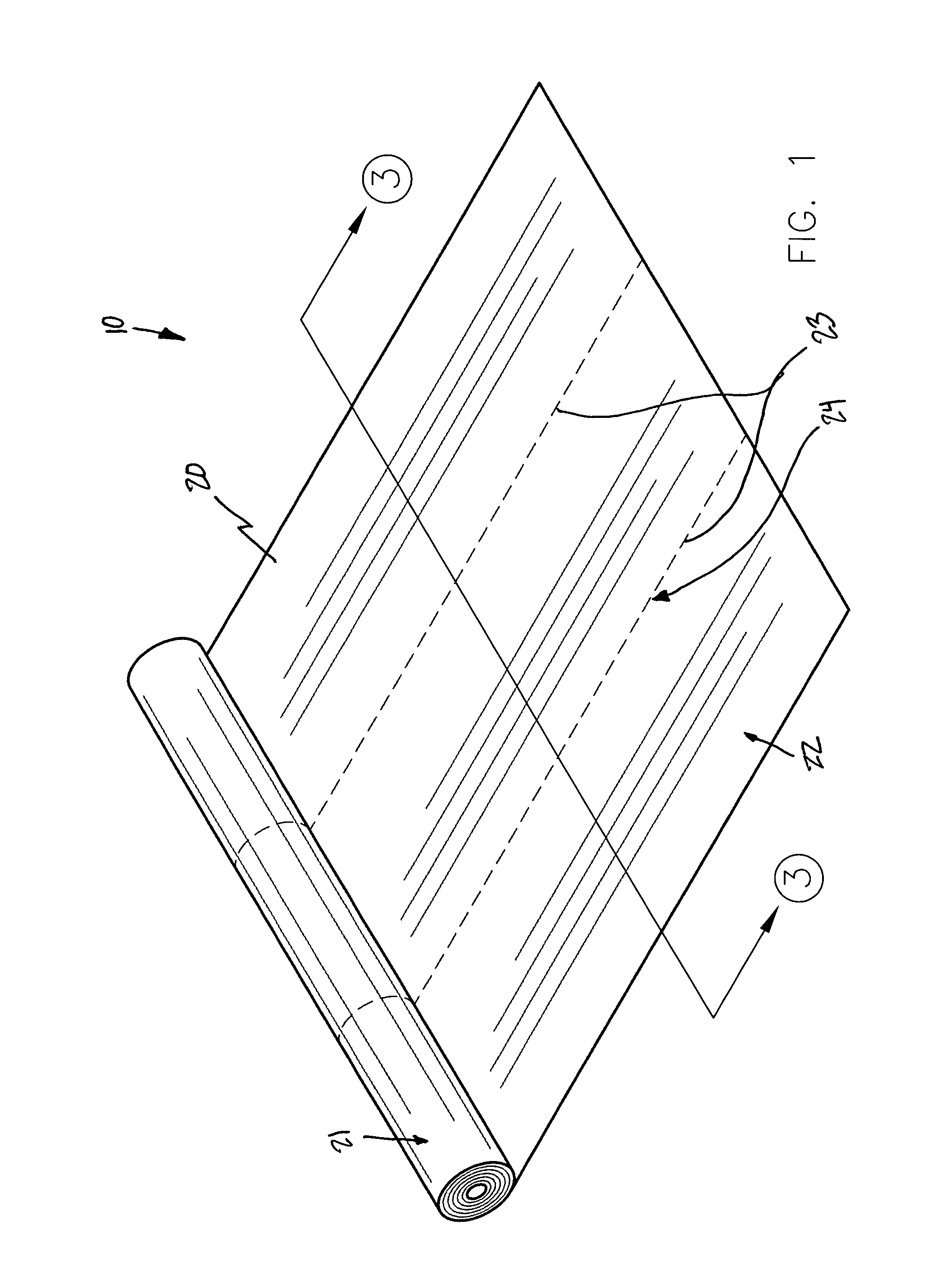
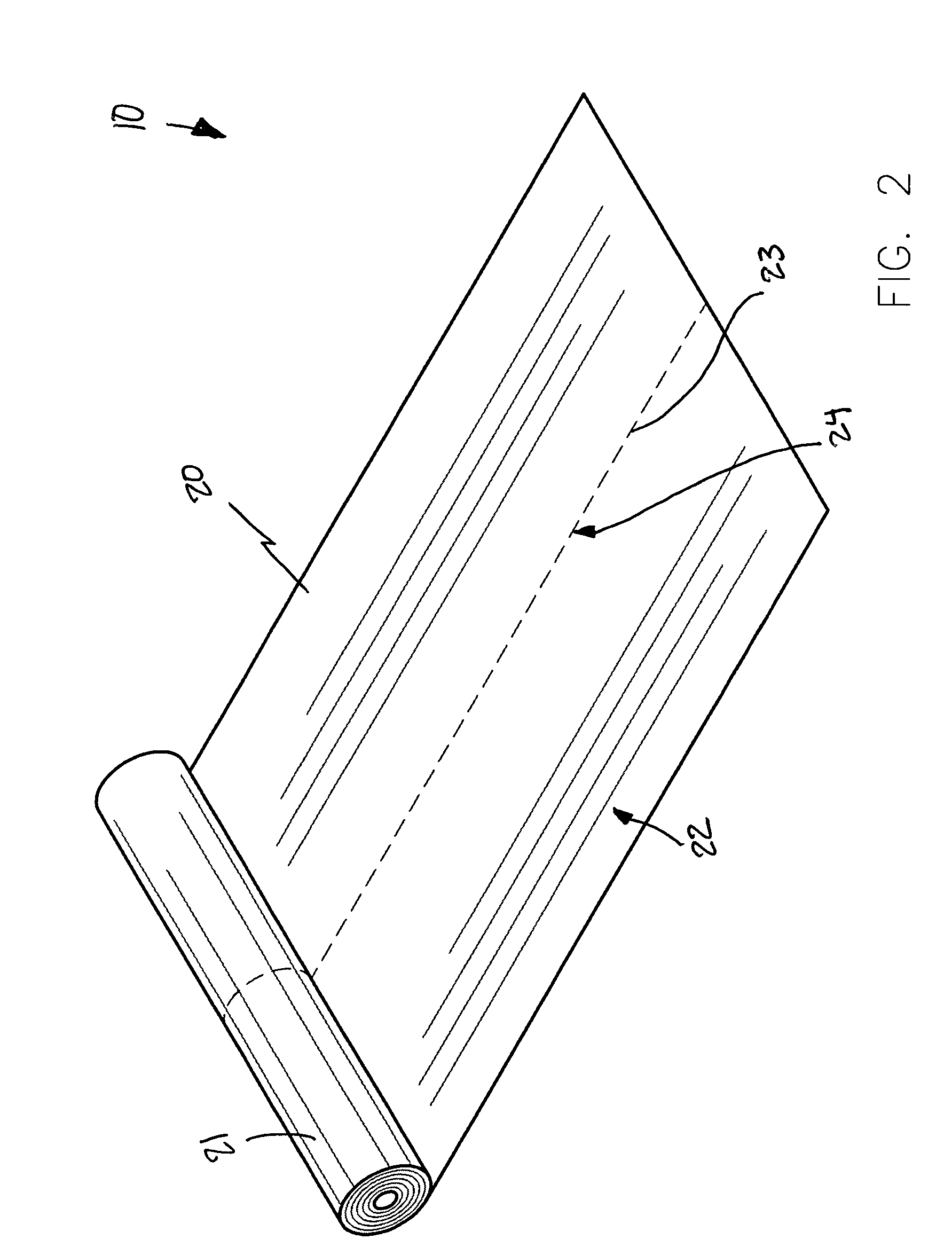
[0029]The apparatus of this invention is referred to generally in FIGS. 1-7 by the reference numeral 10 and is intended to provide a paint protection apparatus. It should be understood that the apparatus 10 may be used to protect many different types of surfaces from many different types of substances and should not be limited in use to protecting only those surfaces from those substances described herein.

[0030]Referring to FIGS. 1, 2, 3, 4, ...


PUM


Abstract

A paint protection apparatus includes a body formed from paint-impermeable material configured in a wound and tubular configuration, and having integrally coupled outer and inner layers covering an entire surface area thereof. The inner layer is formed from an adhesive material. A plurality of perforations passes through the layers, and extends along the entire longitudinal length of the body. A mechanism separates the body along a linear axis registered orthogonal to a longitudinal length of the body while the body is separated along at least one of the perforations. A mechanism unwinds and dispenses the body while one user hand remains spaced from the unwinding and dispensing mechanism during operating conditions. The separating mechanism is slidably positioned along a longitudinal length of the unwinding and dispensing mechanism.

Description

CROSS REFERENCE TO RELATED APPLICATIONS[0001]This application claims the benefit of U.S. Provisional Application No. 60 / 756,964, filed on Jan. 5, 2006.STATEMENT REGARDING FEDERALLY SPONSORED RESEARCH OR DEVELOPMENT[0002]Not Applicable.REFERENCE TO A MICROFICHE APPENDIX[0003]Not Applicable.BACKGROUND OF THE INVENTION[0004]1. Technical Field[0005]This invention relates to protection apparatuses and, more particularly, to a paint protection apparatus for shielding a target zone from undesirable paint streaks during painting operations.[0006]2. Prior Art[0007]In the past it was customary for painters to use drop cloths or newspapers for protecting areas in a structure that were not to be painted from paint droppings and splatters. These protective methods quite often did not prevent paint from dripping down the wall to the juncture where the wall meets the floor since the drop cloth or other type of paint protection device does not adequately seal the wall or baseboard thereby preventin...

Claims


Application Information

Patent Timeline
Patent Type & Authority Patents(United States)
IPC IPC(8): B05C21/00
CPCB05B15/0456B26D1/045B65H35/0086B65H35/06B05B12/24
Inventor NOBLE, JAMES
Owner NOBLE JAMES
Why Eureka
Try Eureka