Over-center self-adjusting equalizing cap chuck

a self-adjusting, cap chuck technology, applied in the direction of caps, rotating screw stopper insertion, application, etc., can solve the problems of imbalance and affecting the gripping force, and achieve the effect of minimal gripping force, strong gripping force, and efficient gripping of the engagement jaws of the cap chuck

Inactive Publication Date: 2006-11-07
DIAMOND MACHINE WERKS
View PDF16 Cites 16 Cited by
  • Summary
  • Abstract
  • Description
  • Claims
  • Application Information

AI Technical Summary

Benefits of technology

[0012]the central portion having a cavity that accommodates a fastener therein to connect the engagement jaw to the housing and to establish a pivot point of the engagement jaw supporting limited axial rotational movement of the engagement jaw between a first axial position and a second axial position,
[0021]a plurality of engagement jaws, each engagement jaw disposed within one of the pocket areas, the pocket areas defined, in part, by opposing walls each having a bore therein, each engagement jaw having a rear portion, a front portion, and a side periphery, the rear portion having a cavity that accommodates a fastener therein to connect the engagement jaw within the pocket area and to establish a pivot point of the engagement jaw supporting limited axial rotational movement of the engagement jaw between a first axial position and a second axial position within the pocket area,
[0026]The embodiments of the present invention advantageously provide a cap chuck engagement of a work piece with a gripping pressure applied in a direction toward a center-point of the work piece receiving area. This over-center engagement, in torque use, achieves an efficient hold of cap chuck engagement jaws against the work piece with a minimal degree of grip force. This is particularly advantageous because the work piece may be received within the chuck with a desirable minimal or light initial grip force to avoid nicks or abrasion of the work piece's outer periphery, yet in torque use during high-speed spindle capping machine operations, the over-center grip upon the work piece achieves a strong hold during capping or de-capping.
[0027]Further, the cap chucks of the present invention can accommodate eccentricities, deviations, and variations in work piece cap size or characteristics in that the cap chucks are self-adjusting and equalizing by providing engagement jaws which have limited axial rotational movement between first and second axial positions. Such engagement exerts separate and independent points of pressure upon a work piece in the same axial plane until the pressure thereon is equalized to insure undamaged concentric alignment during capping operations.
[0028]Still further, the present invention can also provide a more direct angle of contact of the engagement jaw to the work piece accommodating even finely serrated bottle caps without contact point slippage over bottle cap splines.
[0029]Still further, the cap chucks of the present invention provide a simplified means without resorting to complex internal moving parts by which a high performance precision equalizing chuck can be adapted for use in high speed applications without adversely effecting the clamping force generated thereby.

Problems solved by technology

For example, an imbalance may cause improper machining which results in rejection of the work piece.
Alternatively, an imbalance may create a change in the gripping force as a result of the centrifugal force created by the rotation of the gripping jaw.

Method used


Image

  • Over-center self-adjusting equalizing cap chuck
  • Over-center self-adjusting equalizing cap chuck
  • Over-center self-adjusting equalizing cap chuck

Examples


Embodiment Construction

[0048]The following description of the preferred embodiments is merely exemplary in nature and is in no way intended to limit the invention, its application, or uses.

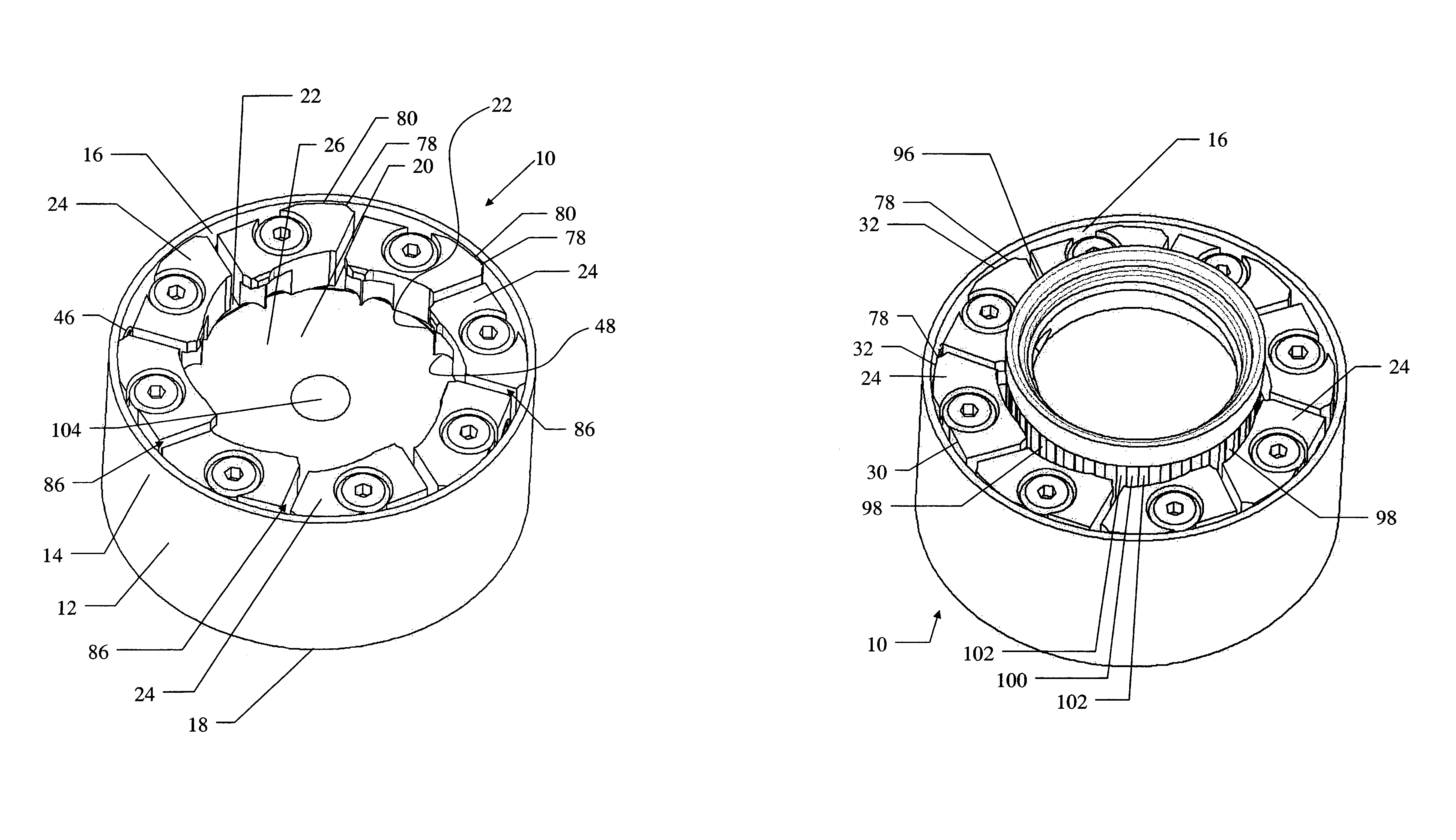
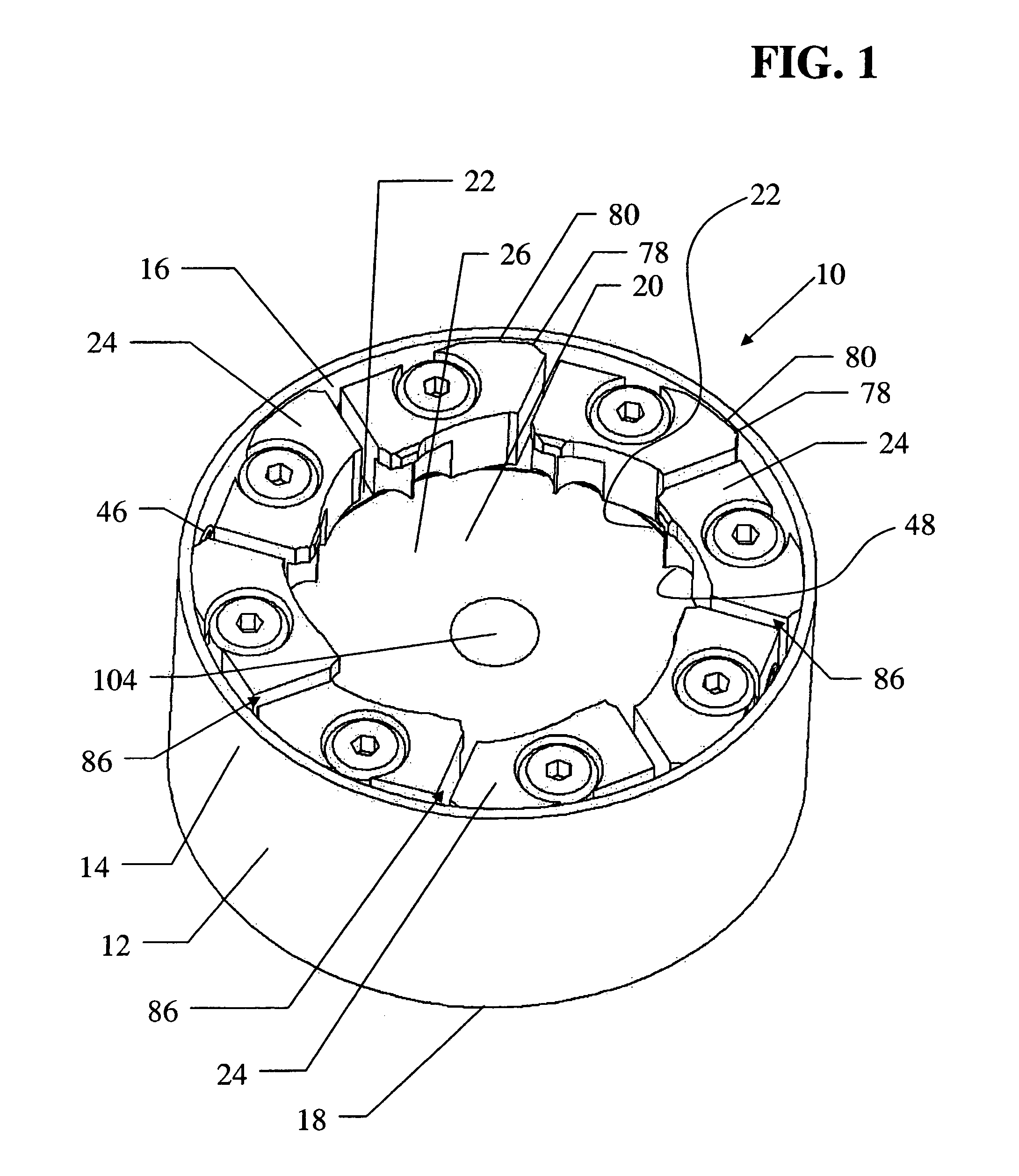
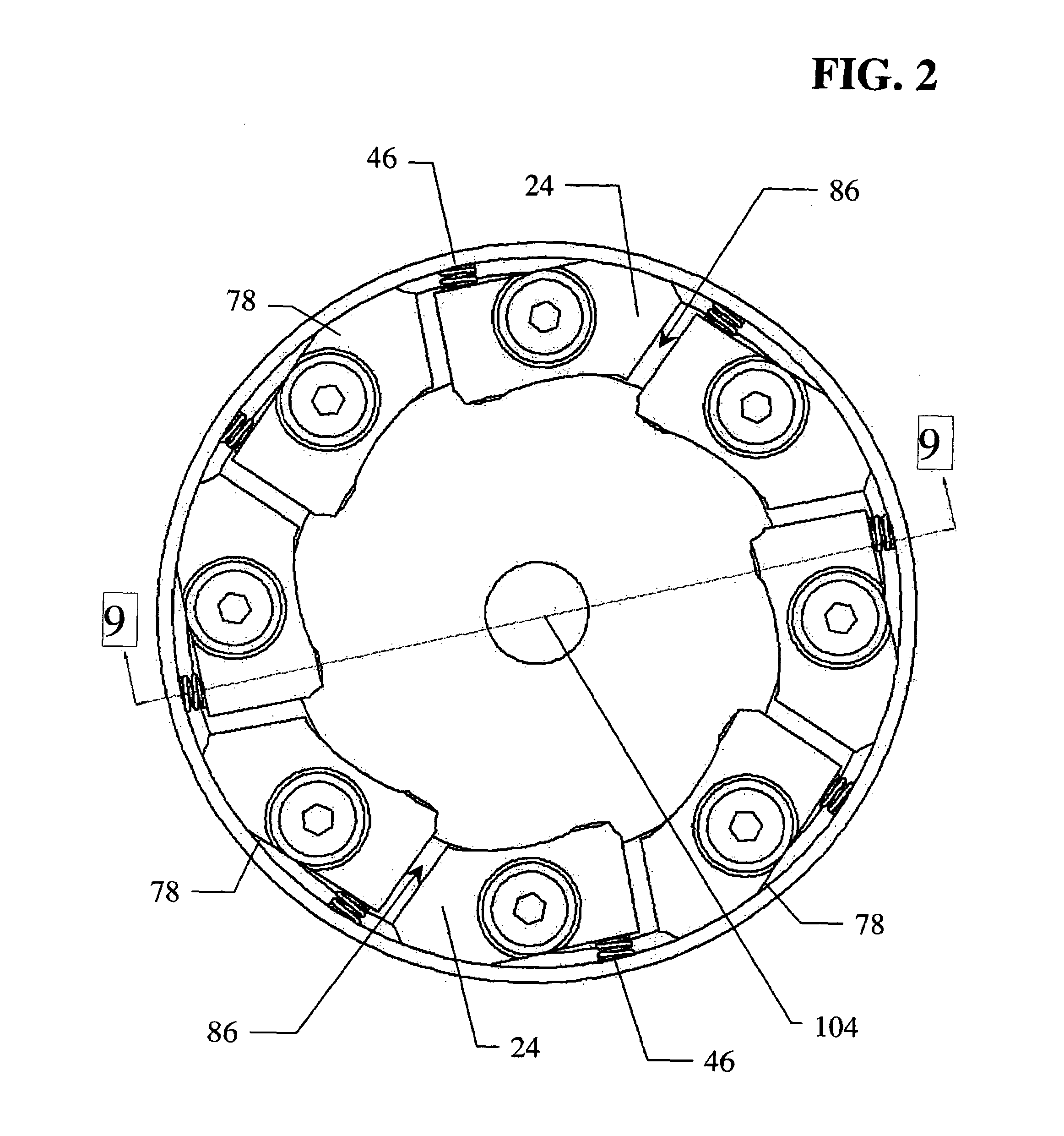
[0049]Referring now to FIG. 1, there is shown an over-center, self-adjusting, equalizing cap chuck 10 constructed in accordance with the teachings of the present invention. The chuck 10 includes a housing 12 that is generally cylindrical in shape. The housing 12 is preferably made of a light-weight metal material, such as aluminum. The housing 12 has an outer annular peripheral surface 14 that defines an inner annular periphery 16 and includes an external face 18 and an internal face 20. The internal face 20 includes an annular area 22 bordering the inner annular periphery 16. As best observed in relation to FIG. 9 discussed hereinafter, the external face 18 is adapted for operative attachment to a spindle assembly of a capping machine. A plurality of engagement jaws 24 are aligned along the annular area 22 to form a bo...


PUM


Abstract

An over-center self adjusting cap chuck adapted for operative attachment to a high-speed capping machine includes a housing having an outer peripheral surface defining an inner annular periphery with an interior face. A plurality of independent engagement jaws are aligned along an annular area of, or within a pocket area of, the interior face. Each engagement jaw has a fastener to connect the engagement jaw to the housing and establish a pivot point to support a limited axial rotational movement thereof to a first open axial position and a second closed axial position for receiving and gripping a work piece respectively. Either a singular bias spring or a pair of bias springs pre-dispose the engagement jaws to the first open axial position. The engagement jaws include an upper beveled area above a work piece engagement finger that serves as an actuator when contacted by a work piece for self-adjusting movement to the second closed axial position whereby the gripping pressure upon the work piece is direct toward a center-point of a work piece receiving area until the pressure thereon is equalized.

Description

BACKGROUND OF THE INVENTION[0001]1. Field of the Invention[0002]The present invention relates generally to chucks, and more particularly to an over-center self-adjusting, equalizing cap chuck adapted for high-speed capping operations of bottle caps, especially bottle caps having a serrated outer periphery.[0003]2. Description of the Related Art[0004]The filling and capping process generally entails supplying containers along a conveyor, automatically filling them at a filling station, and automatically capping them at a capping station. Various testing and control functions may also be performed along the way. The apparatus that performs the process must be capable of accommodating a wide variety of containers and caps (both caps and containers may vary in size and shape), and this is accomplished by a universal chuck which allows quick and easy grasping and manipulation of different cap sizes.[0005]Current common methodology for screw cap positioning and torque include the tapered ...

Claims


Application Information

Patent Timeline
Patent Type & Authority Patents(United States)
IPC IPC(8): B67B3/20B65B7/28
CPCB67B3/2066Y10T279/17213Y10T279/18
Inventor JOERG, ANDREAS WILHELMWILKE, THOMAS ALAN
Owner DIAMOND MACHINE WERKS
Why Eureka
Try Eureka