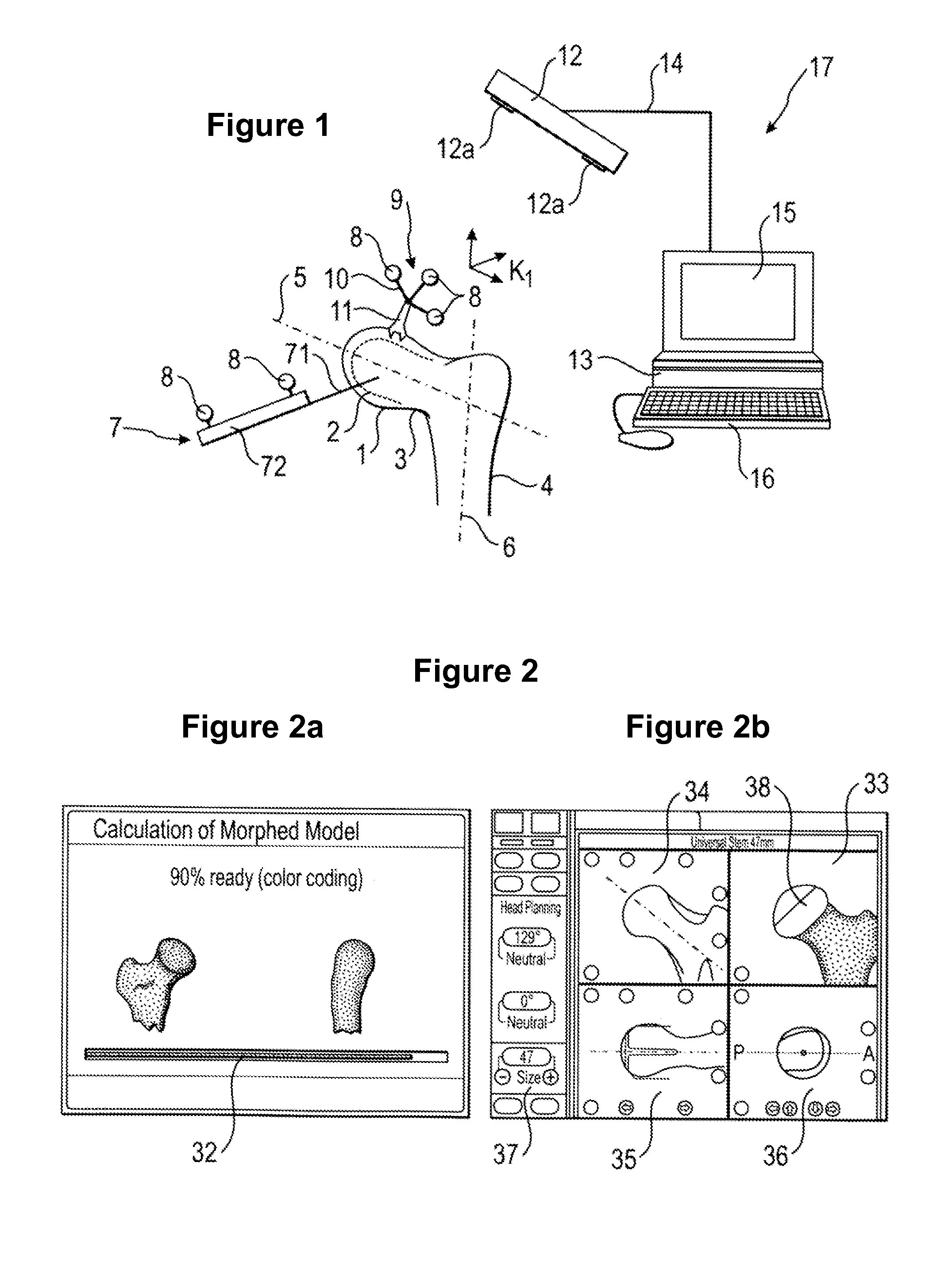
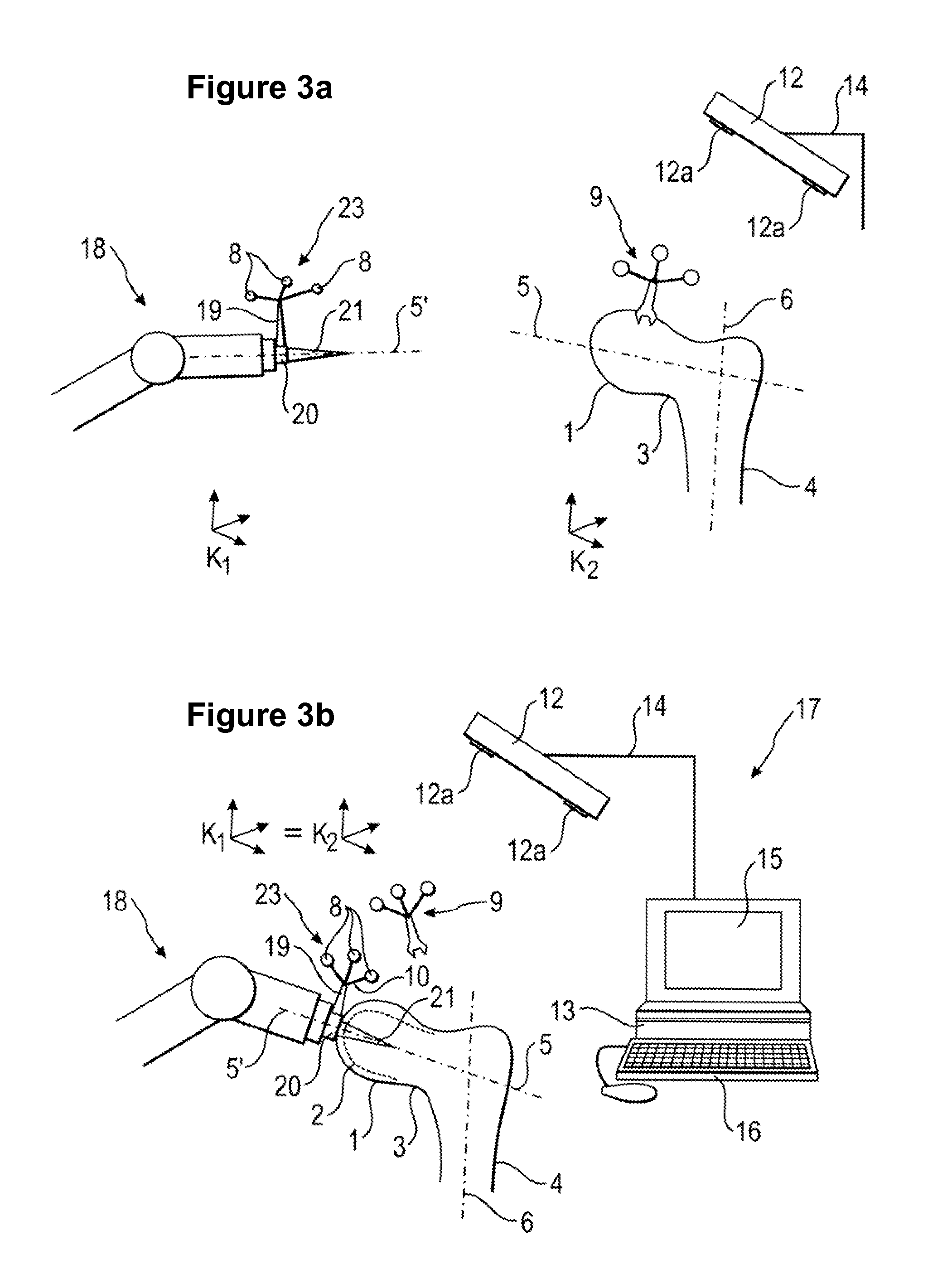
[0013]A “marker holder” is understood to mean a way of attaching an individual marker, which serves to attach the marker to an instrument, a part of the body and / or a holding element of a reference star, wherein the attachment can be stationary and advantageously detachable. The shape of a marker holder can for example be rod-shaped and / or cylindrical. A way of fastening the marker device (such as for example a latch mechanism), which assists in seating the marker device on the marker holder in a force fit and / or positive fit, can be provided at the end of the marker holder which faces the marker.
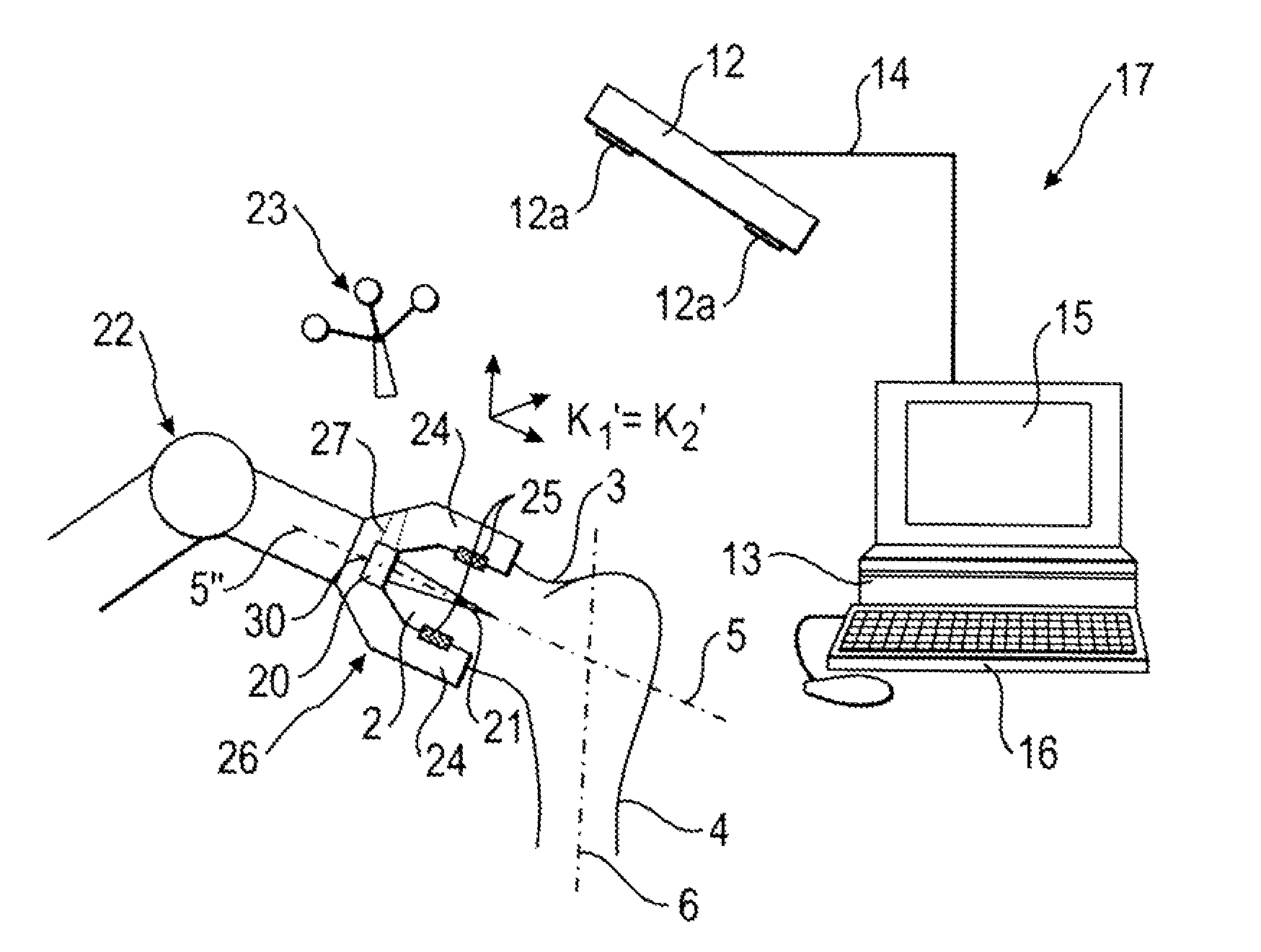
[0016]The fraising head guide allows the tool attachment to be (detachably) mechanically connected (in particular coupled) to the fraising head guide, such that a fixed mechanical connection (which is in particular stationary and / or detachable) between the tool attachment and the femoral head—mediated by the fraising head guide—results. This assists and in particular ensures that during machining, the position of the tool attachment is fixed relative to the femoral head and / or the surface to be machined, in particular even when the surface to be machined is spatially moved, wherein the fraising head guide is preferably configured such that when it is connected to the tool attachment, the movements (for example, rotation) of the at least one machining section which are necessary for machining the femoral head are not impeded.
[0019]When the machining section is applied to the bone, the guide marker device is preferably still fastened to the fraising head guide. In order for the tool attachment to be able to enter into the mechanical connection with the fraising head guide as described above, a cavity for inserting a marker device can be provided on the tool attachment. The marker device is advantageously the guide marker device, which is preferably attached to the fraising head guide such that it is stationary relative to the fraising head guide. The cavity in particular assists in seating the tool attachment, such that it is detachable and stationary, relative to the guide marker device. The cavity can be molded into a surface of the tool attachment as a depression. It can however also be formed as a channel through the tool attachment, in order to enable the guide marker device to be inserted. The cavity advantageously has the shape of a slot in the tool attachment which extends parallel to a longitudinal axis and / or rotational axis (in particular, a cylindrical axis) of the tool attachment. The cavity and the guide marker device (in particular, a holding element of the guide marker device) are advantageously designed such that they are at least partially congruent with respect to each other. This assists in fixedly seating the tool attachment mechanically on the guide marker device, in particular in a positive fit. It is advantageously seated such that it is detachable. It is equally possible in accordance with the invention to design the cavity such that it is at least partially congruent with respect to the fraising head guide. This assists in fixedly seating the tool attachment mechanically on the fraising head guide, in particular in a positive fit, by means of the cavity, if a component of the fraising head is also inserted into the cavity, in particular in addition to a component of the guide marker device. This enables the tool attachment to be seated on the guide marker device and / or the fraising head guide with zero clearance; in particular, a rotationally fixed and advantageously detachable connection between the tool attachment and the guide marker device and / or fraising head guide is established and / or assisted. The slot is advantageously open where it points in the direction of the femoral head, such that a bone marker device arranged on the femoral head or a guide marker device can be moved in the tool attachment and / or inserted into the tool attachment during the applying procedure. The cavity can be molded into a supporting section and / or a machining section of the tool attachment.
[0022]Advantageously, the connecting section assists in seating the at least one machining section, such that it is stationary, relative to the femoral head by being in contact with the guide marker device and / or the fraising head guide. In accordance with one embodiment, the connecting section is provided for fixedly, mechanically and detachably connecting to the fraising head guide. This connecting section can be provided as an alternative to or in addition to the aforesaid cavity provided in the machining section. The cavity can also be provided in the connecting section, as described above. Thus, in accordance with one embodiment, the connecting section can at least partially comprise the cavity. This is particularly advantageous if a detachable mechanical connection between the tool attachment and a component of the guide marker device is to be established. For if the guide marker device and the fraising head guide are mechanically connected to each other in a sufficiently stable way, it is possible to dispense with establishing a direct detachable mechanical connection between the connecting section and the fraising head guide in order to machine the part of the bone.
[0026]The location of the cavity can be adjustable relative to the tool attachment (in particular, relative to the supporting section). A slot-shaped cavity can for example be arranged in a part of the tool attachment which can be shifted relative to other components of the tool attachment. The slot can thus for example be arranged in a plate which is inserted into the supporting section and / or the machining section, coplanar with a surface of the supporting section and / or a machining section and / or the connecting section, and can be shifted within the supporting section and / or connecting section and / or machining section. This enables the cavity to be adjusted exactly to the position of the guide marker device which is to be inserted into it, while being simultaneously independent of for example particular bone shapes. It is thus also possible to apply the cavity to the marker device, if the part of the bone to be machined exhibits a geometry which is difficult to encompass using the tool attachment.


