Physically small antenna

Inactive Publication Date: 2005-02-15
NEC CORP
View PDF11 Cites 5 Cited by
  • Summary
  • Abstract
  • Description
  • Claims
  • Application Information

AI Technical Summary

Benefits of technology

Therefore, an object of the present invention is to provi

Problems solved by technology

An instrument including an antenna that constitutes a wireless LAN system is ofte

Method used


Image

  • Physically small antenna
  • Physically small antenna
  • Physically small antenna

Examples


Embodiment Construction

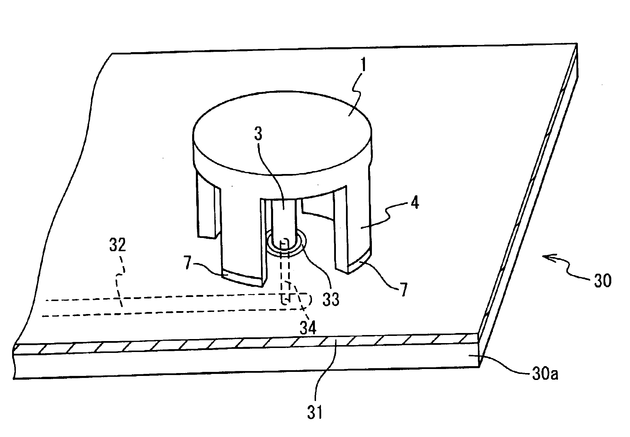
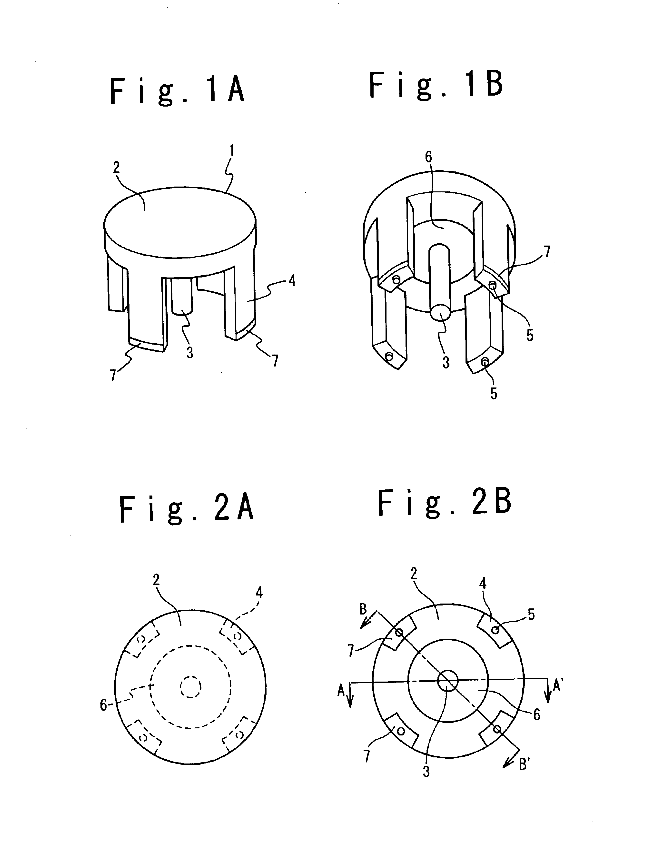
FIGS. 1A and 1B show an antenna in an embodiment of the present invention. The antenna 1 includes a dielectric plate 2, a cylindrical vertical element 3, and a conductive plate 6. As shown in FIGS. 2A and 2B, the dielectric plate 2 and the conductive plate 6 are circular. The vertical element 3 and the conductive plate 6 are coaxially disposed on the rear surface of the dielectric plate 2. The vertical element 3 extends in a direction perpendicular to the rear surface of the dielectric plate 2 without penetrating the dielectric plate 2.

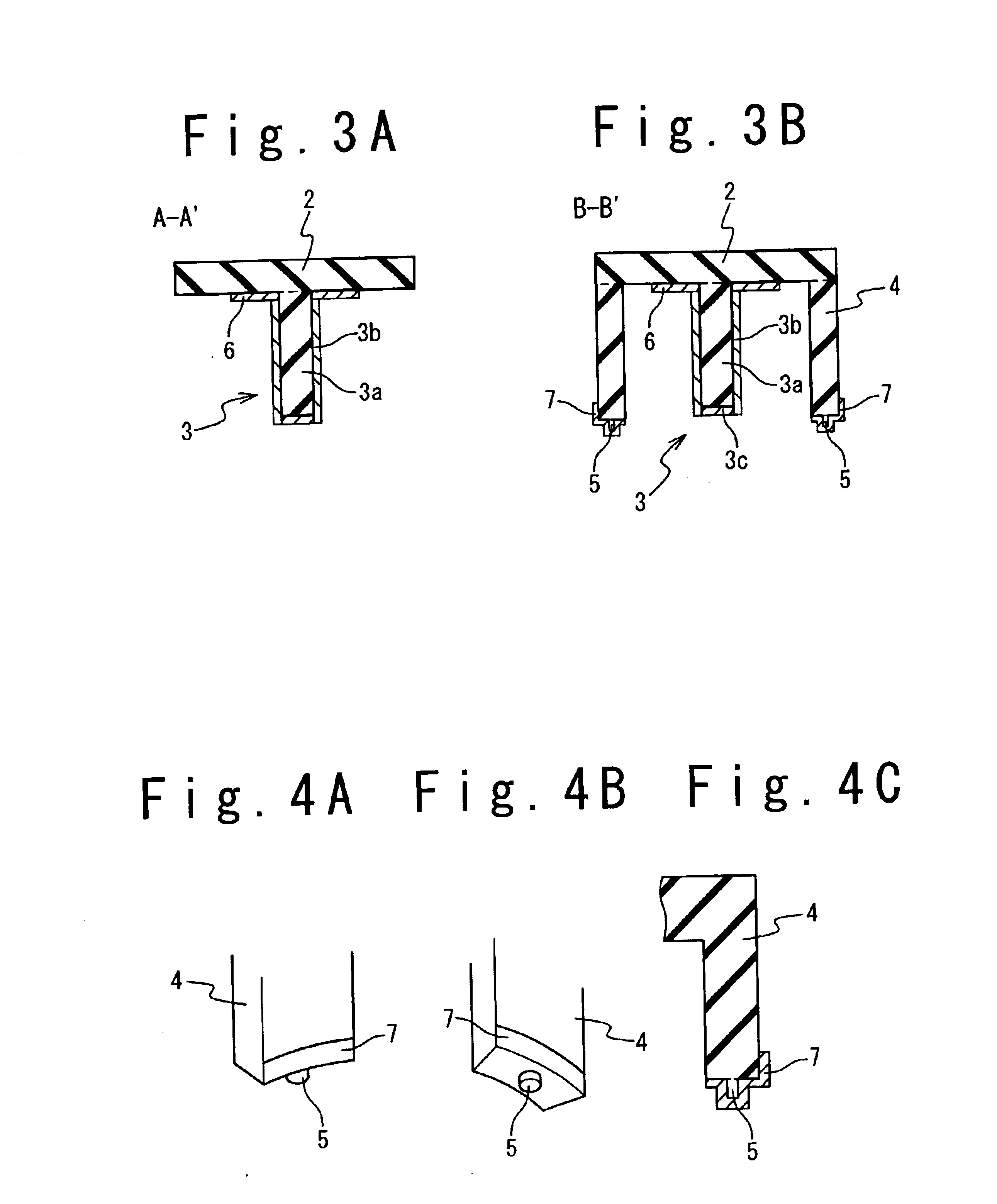
As shown in FIGS. 3A and 3B, the vertical element 3 includes a cylindrical dielectric bar 3a, and a cylindrical conductive shell 3b. The dielectric bar 3a is disposed in contact with the rear surface of the dielectric plate 2 at one of the ends through a hole provided for the conductive plate 6. The other end and the side of the dielectric bar 3a are covered with the conductive shell 3b. One of the ends of the cylindrical conductive shell 3b is attach...


PUM


Abstract

A physically small antenna having a wide bandwidth that facilitates the inspection of the attachment to the printed circuit board. The antenna is provided with a dielectric plate having a rear surface, a conductive plate disposed on the rear surface, a vertical element extending in a direction perpendicular to the rear surface. The vertical element includes a dielectric bar, an end of which is attached to the rear surface, and a conductive shell covering a side and an opposite end of the dielectric bar to be attached to the conductive plate.

Description

BACKGROUND OF THE INVENTION1. Field of the InventionThe present invention relates, in general to an antenna, more particularly to a physically small surface mount type antenna.2. Description of the Related ArtThe development of wireless local area network (wireless LAN) technologies increases demand for physically small antennas. An instrument including an antenna that constitutes a wireless LAN system is often required to be small, and this heightens the need for physically small antennas. Physically small antennas suitable for wireless LAN systems are disclosed in Japanese Open Laid Patent Application (Jp-A-Heisei 8-84019, Jp-A-Heisei 8-97626, Jp-A-Heisei 9-74308, Jp-A-Heisei 9-74309, and Jp-A-Heisei 10-41736) and Japanese Registered Utility Model Gazette (Jp-U 3041690). “Antennas and Radio Propagation”, which is published by Corona Publishing Co., Ltd. in Japan, discloses in pages 69 and 70 that top-loading effectively reduces the size of the antenna.An antenna used in a wireless...

Claims


Application Information

Patent Timeline
IPC IPC(8): H01Q1/38H01Q9/04H01Q9/36H01Q13/08H01Q1/12H01Q9/40
CPCH01Q9/36H01Q1/38
Inventor KURAMOTO, AKIOTANABE, KOUSUKEKOIZUMI, TAKAO
Owner NEC CORP
Why Eureka
Try Eureka