
Self-assembling wireless network, vehicle communications system, railroad wheel and bearing monitoring system and methods therefor

a wireless network and self-assembling technology, applied in the field of networked wireless communications, can solve the problems of inflexible system ids, failure to pick up nodes, and low reliability of commercial communication bands,

Active Publication Date: 2010-04-27
CONVEY INC
View PDF25 Cites 89 Cited by
  • Summary
  • Abstract
  • Description
  • Claims
  • Application Information

AI Technical Summary

Benefits of technology

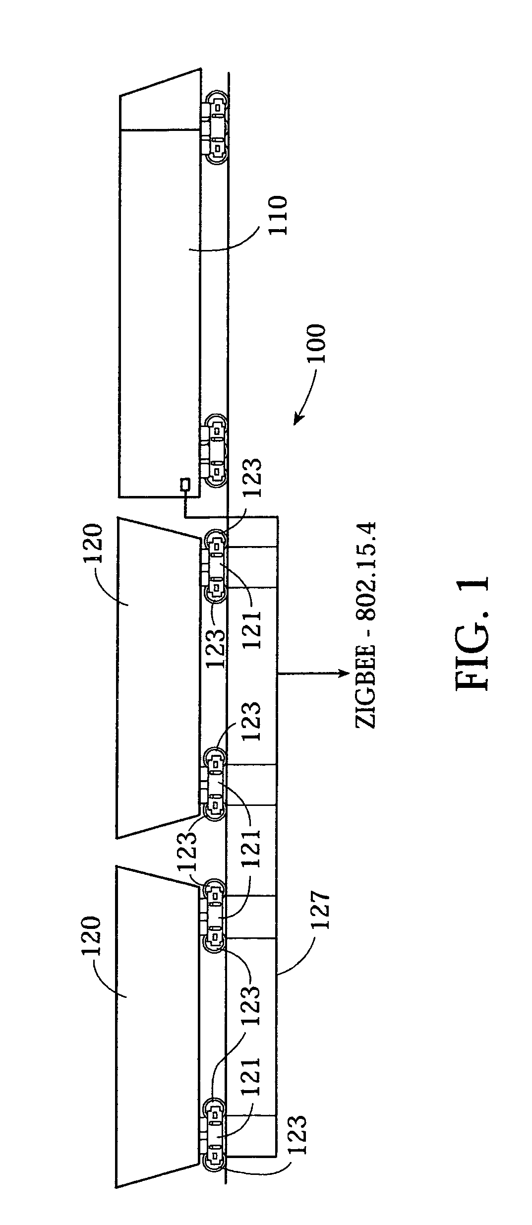
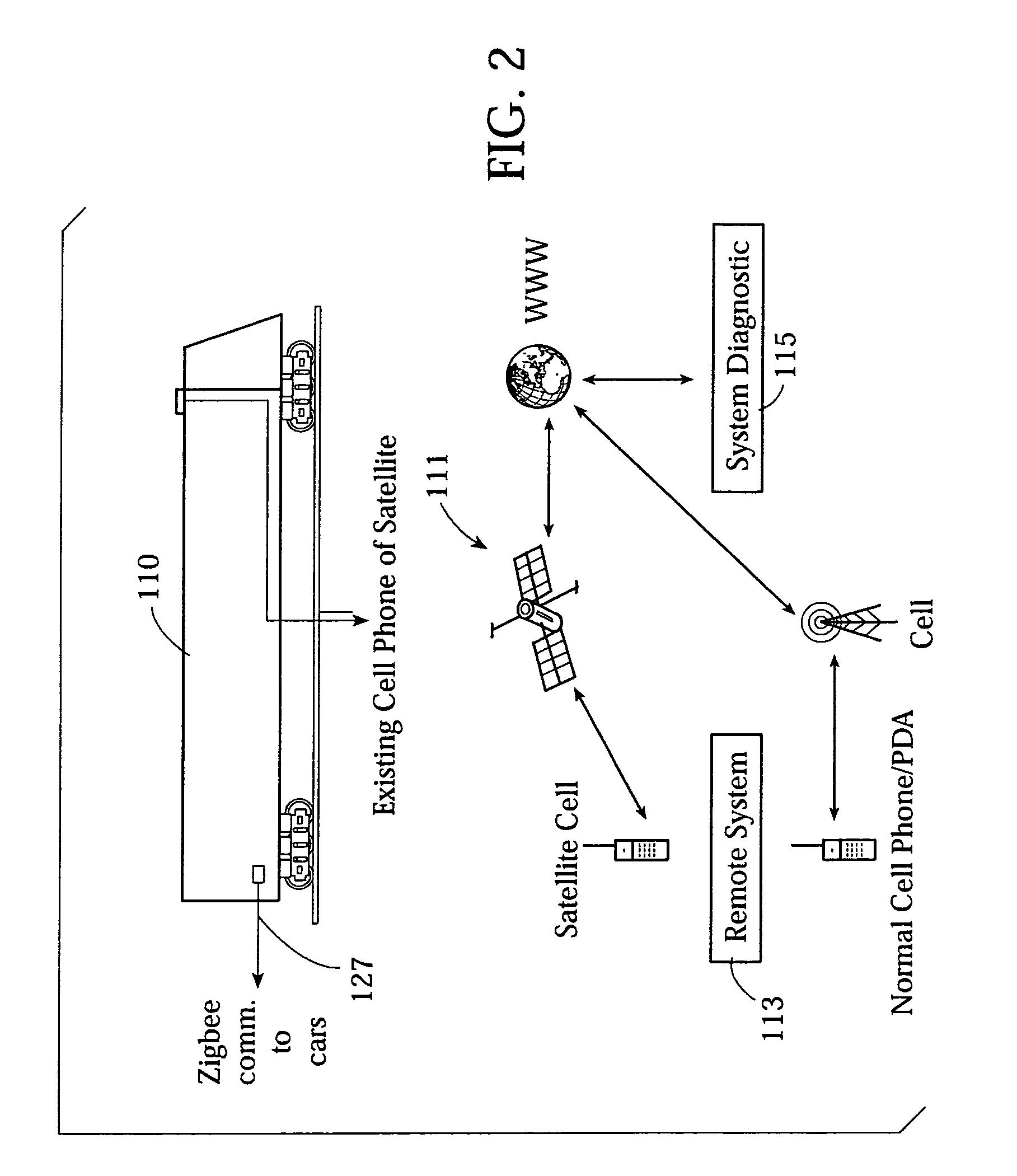
"The present invention provides a network system and method that overcomes the limitations of prior art networks. The network system is made up of multiple wireless communication nodes that form a low power wireless network. The nodes have sensors that detect physical parameters in the environment and a microprocessor that analyzes the sensor data and derives therefrom bearing condition data corresponding to a degradation condition of the bearings of the wheel assembly. The nodes can communicate with each other and are retained in the network only if the rotation rate of the wheel is consistent with the railcars moving together in the train. The network system uses Bluetooth or Zigbee for communication among the nodes and can self-assemble from a plurality of individual nodes based on common environmental or stimulus. The method uses wide bandwidth, high-speed data acquisition and distributed signal processing to acquire and analyze the sensor data on the nodes and transmit the results over the network. The invention allows for wide bandwidth sensors to be used without the need for wide bandwidth wireless communication or data compression."

Problems solved by technology

Systems that access all nodes in range may include unnecessary nodes that use up bandwidth of the network.
Bandwidth is an issue in common networks, which do not address wide bandwidth signal acquisition due to monitoring hardware and wireless communication bandwidth limitations.
The common commercial communication bands, e.g., Bluetooth and Zigbee, do not support wide bandwidth transmission.
Wide bandwidth transmissions are generally only provided by military wireless bands or by expensive commercial civilian bands.
On the other hand, systems relying on node IDs are inflexible and may fail to pick up nodes that appropriately should be in the network due to various reasons, such as a failure to include a particular node ID in the list of nodes, or based on a lack of information that the node should be in the network.
In the specific area of railroad cars, no suitable systems exist for properly monitoring them in real time, particularly in the area of monitoring wear and performing predictive maintenance of the bearings of the railroad cars.
Bearing failures of individual railcars are responsible for expensive and potentially disastrous derailments.
These systems can be said to work adequately for the vast majority of existing rolling stock applications, but, as speed of the passing railcars increases, there is less and less time to detect and react to potential problems, since these systems do not provide continuous real-time data.
This could theoretically be improved by increasing the number (and thus decreasing the distance) between wayside monitoring systems, allowing more communication with each railcar, but this involves substantial cost associated with installation and maintenance of the trackside detectors.
However, these earlier efforts or devices did not address:Ease of use and installationLong power life or power generationOnboard data processing yielding OK, Caution or Danger statusViable communication schemes.
A substantial problem is that wireless systems of the prior art that perform on-board monitoring require substantial amounts of electrical energy to power them.
Due to the duration of use of railway cars, the long distances they cover, and the fact that they do not usually have their own source of electrical energy, these systems are not optimal.

Method used


Image

  • Self-assembling wireless network, vehicle communications system, railroad wheel and bearing monitoring system and methods therefor
  • Self-assembling wireless network, vehicle communications system, railroad wheel and bearing monitoring system and methods therefor
  • Self-assembling wireless network, vehicle communications system, railroad wheel and bearing monitoring system and methods therefor

Examples


example

[0297]A railcar equipped with a unit similar to unit 401, but with a computer recording its sensory data instead of a wireless network connection, was subjected to an experimental trip to determine whether the sensor data acquisition, especially using MEMS sensors, could be used to monitor rail car bearings.

[0298]FIGS. 14A and B show time-domain graphs of the raw accelerometer data from the sensor unit at ambient (the steady horizontal lines) and at speed (the noisier lines) over a time period of 1.92 seconds. This shows the degree of vibration in the sensor array.

[0299]FIGS. 15A and B show frequency domain graphs that represent Fourier transforms of the x and y axis ambient frequencies, indicating a system with no accelerations or vibrations in the analyzed range of frequencies.

[0300]FIGS. 16 A and B show Fourier transforms of the x-axis and y-axis accelerometer outputs at speed. It is apparent that there are distinct frequency peaks in the y-axis accelerations at speed, as can be ...


PUM


Abstract

A low power self-organizing network is made up of a plurality of wireless communication nodes communicating wirelessly with each other. The nodes each have a sensor providing a respective sensor data value indicative of a physical parameter in the environment of that node. The wireless network discontinues communication with any nodes in which the sensor data value is outside a range of network sensor data values. The network is preferably a group of vehicles moving together, especially a train in which each node is associated with a respective wheel of a railroad car. The nodes are low-power devices that communicate using wireless communications according to a Zigbee protocol. The nodes each have an additional sensor sensing a physical parameter the respective wheel thereof and determines from said electrical signal a degree of degradation of a bearing of the wheel, and transmits data of the degree of degradation to the main node. The main node communicates with another computer system using a higher power communication system and transmits thereto data indicative of degradation of said bearings.

Description

RELATED APPLICATIONS[0001]This application claims the benefit of U.S. provisional application 60 / 778,502 filed on Mar. 1, 2006, which is herein incorporated by reference in its entirety.FIELD OF THE INVENTION[0002]This invention relates to the field of networked wireless communications, and more particularly to wireless self-assembling networks that assemble communication nodes that each can sense some common environmental parameter. In an especially preferred application, this invention relates to the field of wirelessly networking vehicles, especially where the vehicles are railroad cars, and where the communications are part of a system for monitoring the degree of wear on the wheel bearings of railroad cars.BACKGROUND OF THE INVENTION[0003]In a typical wireless communication application, every active receiver and transmitter in range joins the network, although in some applications ID numbers are assigned to transmitter and receiver nodes so that only nodes with allowed ID numbe...

Claims


Application Information

Patent Timeline
Patent Type & Authority Patents(United States)
IPC IPC(8): G08B21/00
CPCB61L15/0027B61L15/0036B61L15/0081F16C19/52G01D21/00H04L67/12H04W76/06H04W84/005H04W84/06H04W84/18H04W76/30Y04S40/18
Inventor BARONE, GERARD A.BREITFELLER, JASON O.JACOBS, DAVID ANDREWNYQUIST, CHARLES W.ROSE, JR., ROGER E.
Owner CONVEY INC
Learn More