Synchronization of devices in a RFID communications environment

a technology of synchronization and communication environment, applied in the field of data communication, can solve the problems of low degree of precision, high cost, and inability to determine the absolute toa accurately, and achieve the effects of reducing the amount of time, reducing power consumption, and reducing the battery life of the arfid tag

Inactive Publication Date: 2010-11-04
L 3 COMM INTEGRATED SYST
View PDF6 Cites 89 Cited by
  • Summary
  • Abstract
  • Description
  • Claims
  • Application Information

AI Technical Summary

Benefits of technology

[0009]Features that may be implemented in various possible embodiments of the disclosed systems and methods include, but are not limited to, a first band (e.g., Narrow Band Frequency Modulation “NBFM”) channelized interrogator, spatial diversity separation technique, frequency diversity separation technique, and / or multi-band aRFID tags that receive data using a first band of signals (e.g., NBFM signals) and only transmit using a second band of signals (e.g., UWB signals) when interrogated. Further features that may be implemented include, but are not limited to, wireless synchronization of individual aRFID tag circuitry with a first band interrogator to minimize operating time of a first band receiver of the individual aRFID tag.
[0013]In one exemplary embodiment, an adaptive wakeup scheme or methodology may be implemented to allow an aRFID tag to stay synchronized with an aRFIDI system while at the same time optimizing power consumption. Depending on the particular configuration of a given aRFID tag, the battery life of an aRFID tag may be greatly reduced by first band signal receiving operations. Thus, in this exemplary embodiment, a first band receiver (or transceiver) component of an aRFID tag may only be operated when a first band packet is expected from an aRFIDI system, and in a manner that reduces the amount of time between when the first band receiver is turned on and when the first band packet is received (i.e., the receive buffer time). At other times, the aRFID tag may be placed in a low power consumption sleep state. The amount of time that an aRFID tag spends in such a low power sleep state before waking and receiving the following interrogate packet (i.e. when an aRFIDI system is sending out polling packets at a known rate) may also be optionally adjusted, e.g., to fit characteristics of a given situation and / or to re-synchronize a given aRFID tag with first band transmissions from an aRFIDI. Thus, the disclosed systems and methods may be implemented in a manner that allows a given aRFID tag to receive packets from an aRFIDI system within a given receive buffer time, while also correcting for clock drift between the aRFIDI system and the given aRFID tag.

Problems solved by technology

The primary source of error in determining the absolute TOA is the accuracy with which the arrival time of the emitted signal may be measured at each receiver.
Although a high degree of timing accuracy can, in principal, be obtained by employing highly synchronized clocks at each receiver (e.g., using synchronized atomic clocks), this can be a very expensive option.
Use of a cross correlation method is appropriate only for narrow band signals and also lacks a high degree of precision.

Method used


Image

  • Synchronization of devices in a RFID communications environment
  • Synchronization of devices in a RFID communications environment
  • Synchronization of devices in a RFID communications environment

Examples


Embodiment Construction

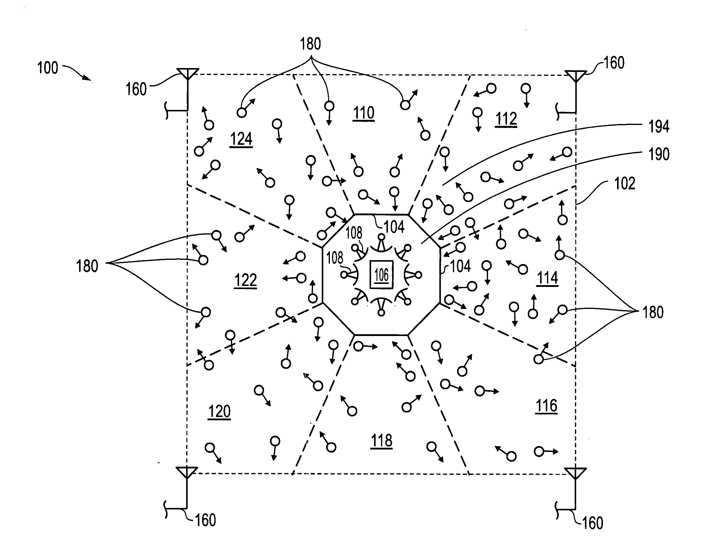
[0026]FIG. 1 illustrates one exemplary embodiment of an aRFID communication system 100 that includes a master coverage area 194 defined between outer boundary 102 and inner boundary 104 of the system 100. In one embodiment such a master coverage area may be, for example 1 mile by 1 mile square, although other sized master coverage areas (both smaller and larger), and / or other shapes of master coverage areas may be implemented in other embodiments. Although an aRFID system and associated devices are described herein, it will be understood that embodiments of the disclosed systems and methods may also be implemented with passive RFID tags and semi-passive RFID tags, as well as RFID communication systems employing the same.

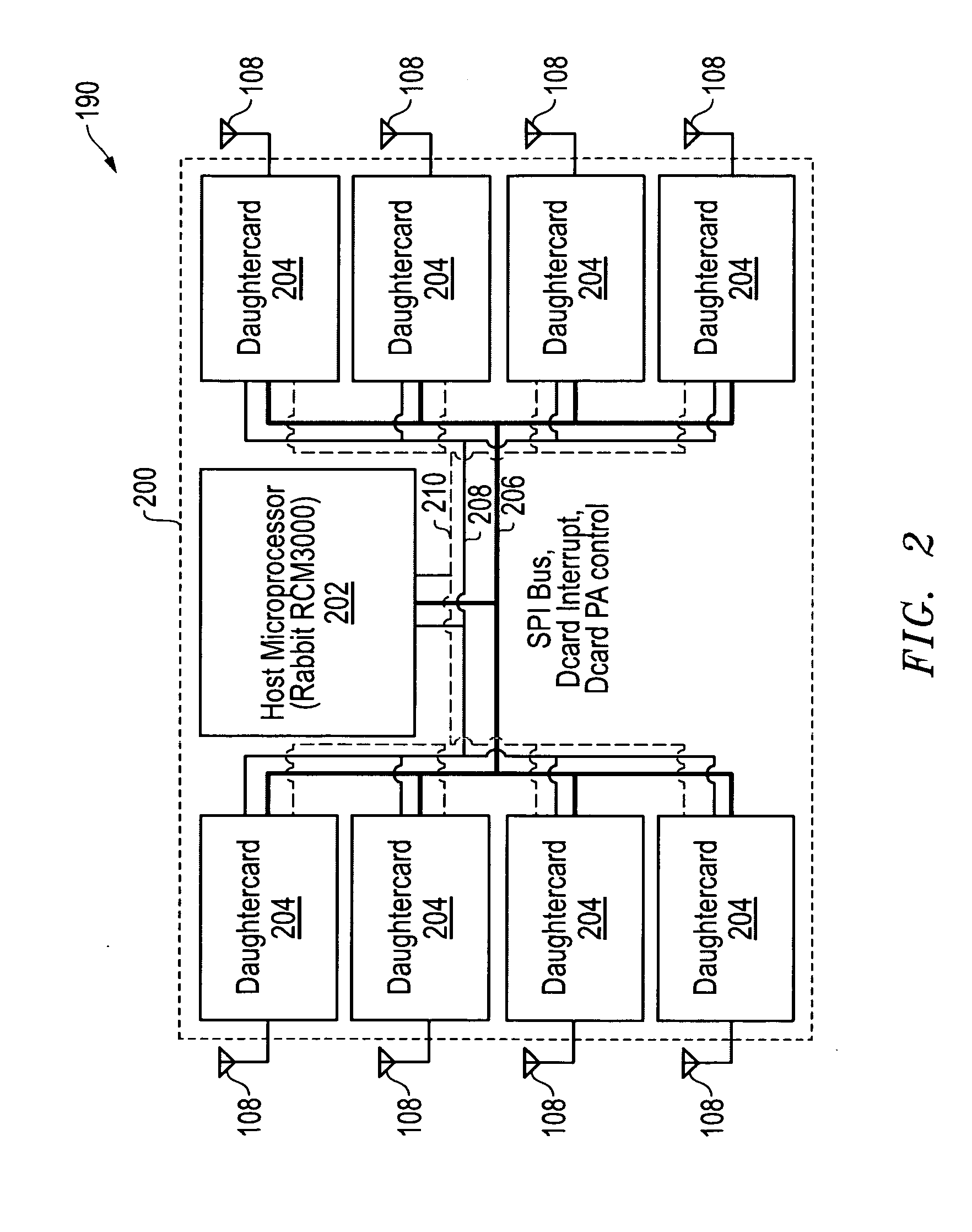
[0027]As shown in FIG. 1, a remote active RFID interrogator (aRFIDI) system 190 with its corresponding directional signal transmission system (e.g., multiple outwardly facing antenna panels) is positioned within the boundaries of (e.g., in this case substantially at ...


PUM


Abstract

An adaptive wakeup methodology may be implemented to allow an radio frequency identification (RFID) tag to stay synchronized with periodic radio frequency (RF) interrogator polling signal while at the same time optimizing power consumption. A receiver (or transceiver) component of a RFID tag may only be operated when an interrogator polling signal is expected, and in a manner that reduces the amount of time between when the receiver or transceiver is turned on and when the interrogator polling signal is received (i.e., the receive buffer time). At other times, the RFID tag may be placed in a low power consumption sleep state. The amount of time that the RFID tag spends in such a low power sleep state before waking and receiving the following interrogator polling signal may also be optionally adjusted, e.g., to fit characteristics of a given situation and / or to re-synchronize a given aRFID tag with first band transmissions from an aRFIDI.

Description

FIELD OF THE INVENTION[0001]This invention relates generally to data communication, and more particularly to separation of data communication in high density environments.BACKGROUND OF THE INVENTION[0002]As defined by the FCC, an ultra-wideband (UWB) signal is an antenna transmission in the range of 3.1 GHz up to 10.6 GHz at a limited transmit power of −41.3 dBm / MHz with an emitted signal bandwidth that exceeds the lesser of 500 MHz or 20% of the center frequency. UWB signals are currently employed for high-bandwidth, short range communications that use high bandwidth radio energy that is pulsed at specific time instants.[0003]Applications for FCC-defined UWB transmissions include distance-based location and tracking applications, and localization techniques that employ precision time-of-arrival measurements. Examples of such UWB applications include radio frequency identification (RFID) tags that employ UWB communication technology for tracking, localization and transmitting inform...

Claims


Application Information

Patent Timeline
Patent Type & Authority Applications(United States)
IPC IPC(8): H04Q5/22
CPCG06K19/0701G06K19/07749G06K19/0723
Inventor BURKART, SCOTT M.BROWN, JONATHAN E.
Owner L 3 COMM INTEGRATED SYST
Why Eureka
Try Eureka