Communication system with a plurality of nodes communicably connected for communication based on NRZ (non return to zero) code

a communication system and plurality of nodes technology, applied in the field of communication networks, can solve the problems of unignorable electric power consumption, inability to exclusively wake up and use necessary nodes, and inability to communicate system-wide, etc., and achieve the effect of increasing the power consumption of nodes

Inactive Publication Date: 2012-03-01
NIPPON SOKEN +1
View PDF4 Cites 88 Cited by
  • Summary
  • Abstract
  • Description
  • Claims
  • Application Information

AI Technical Summary

Benefits of technology

[0015]In light of the problems set forth above, it is desired that a communication system is able to individually wake up nodes which are in a sleep mode, and an activation frame of a node in question is identified without increasing power consumption of nodes which are in a sleep mode.

Problems solved by technology

A communication system having such a wake-up / sleep function suffers from a problem in the case where some nodes are in a sleep mode (hereinafter, such a node is referred to as a “suspended node”).
Further, in such a case, it has been a problem that necessary nodes cannot be exclusively woken up and used.
Thus, in spite of being suspended nodes (not being activated as ECUs), unignorable electric power is problematically kept being consumed.

Method used


Image

  • Communication system with a plurality of nodes communicably connected for communication based on NRZ (non return to zero) code
  • Communication system with a plurality of nodes communicably connected for communication based on NRZ (non return to zero) code
  • Communication system with a plurality of nodes communicably connected for communication based on NRZ (non return to zero) code

Examples


first embodiment

[0065]With reference to FIGS. 1-12, a first embodiment will now be described.

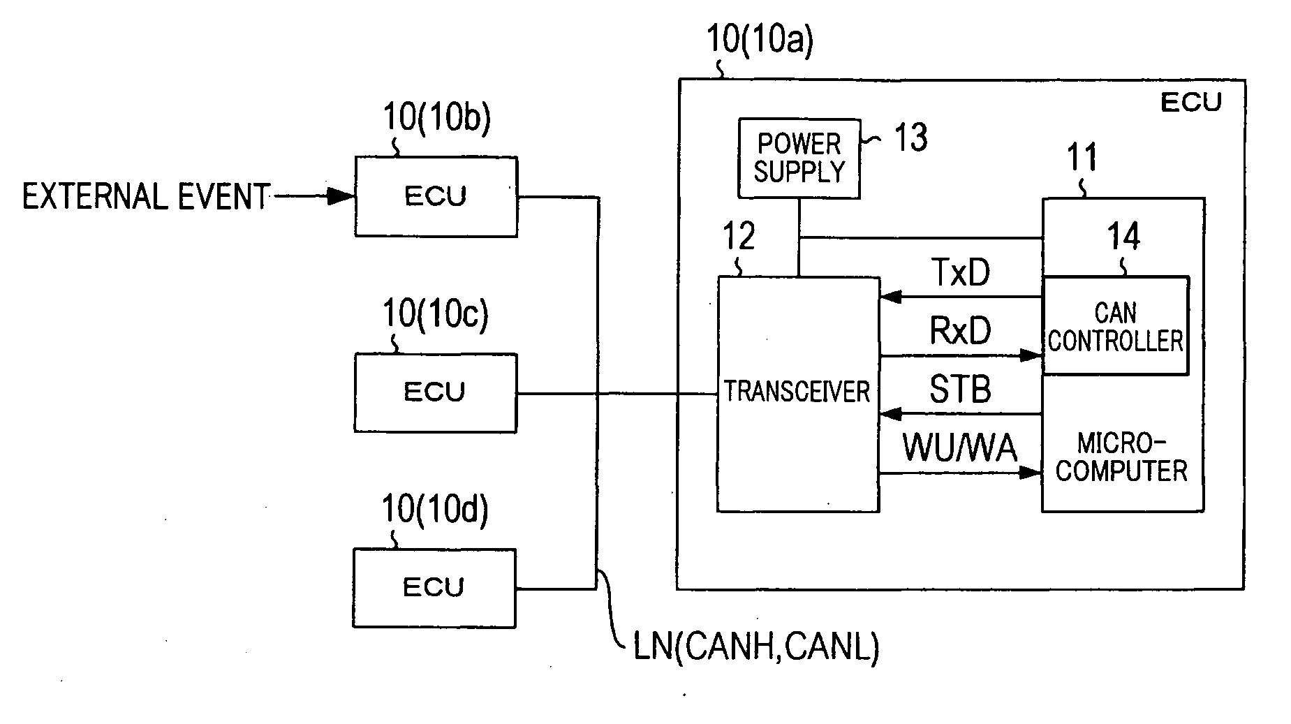
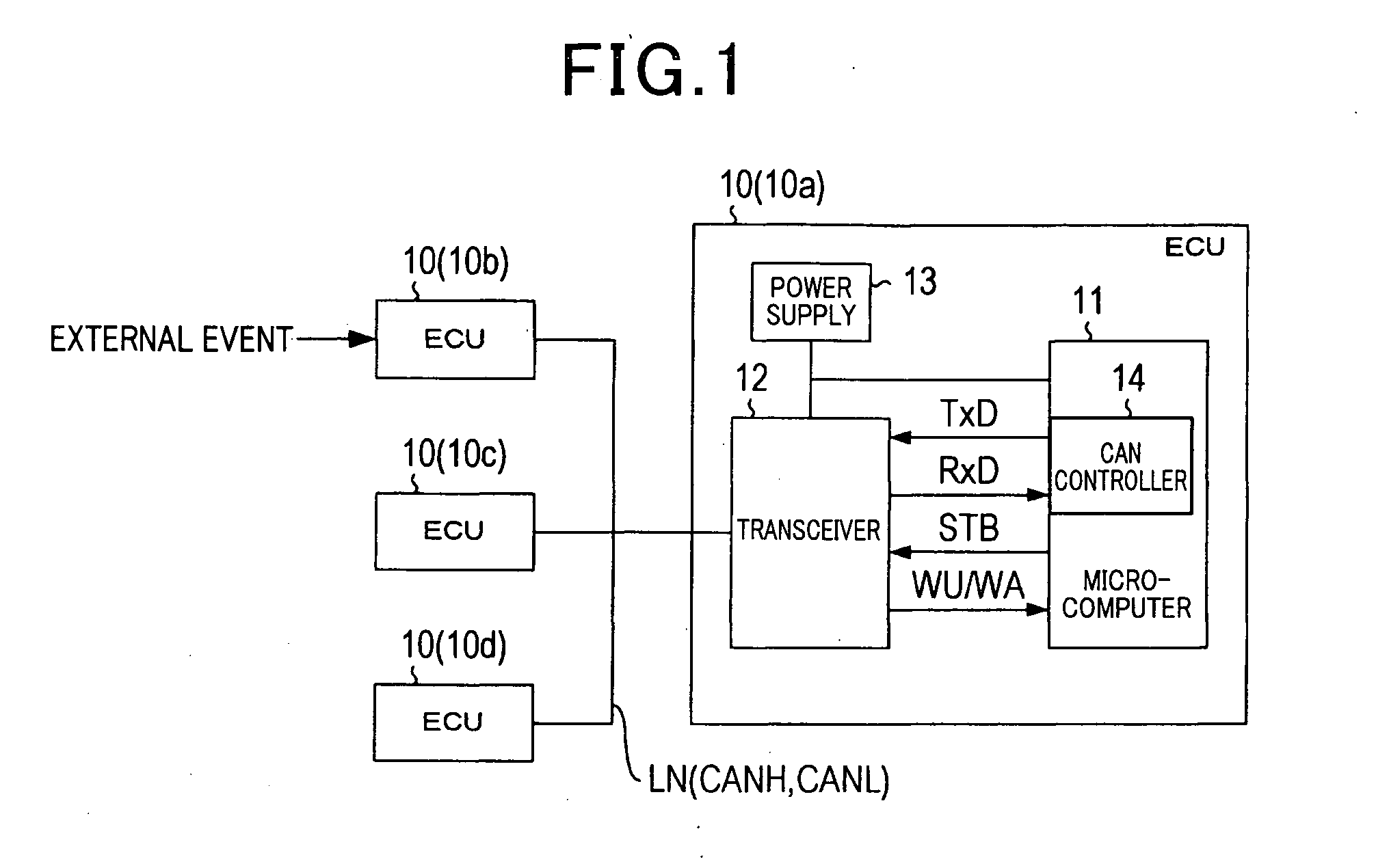
[0066]FIG. 1 is a block diagram illustrating an on-vehicle configuration of a communication system 1 that uses a CAN (Controller Area Network) protocol as a communication protocol.

[0067]As shown in FIG. 1, the communication system 1 is configured connecting a plurality of electronic control units 10a, 10b, 10c, . . . installed in a vehicle via a common communication channel LN so that the electronic control units can communicate with each other. In the communication system 1, each of these electronic control units 10a, 10b, 10c, . . . functions as a node. In the description set forth below, these electronic control units are referred to as “ECUs 10a, 10b, 10c, . . . ”. Further, when one or some of these ECUs 10a, 10b, 10c, . . . is / are mentioned without particularly indicating specific reference numerals, or mentioned as representative(s), the ECU(s) is / are referred to as “ECU(s) 10”.

[0068]The communication...

second embodiment

[0173]Referring to FIGS. 13-19, a second embodiment of the present invention will now be described.

[0174]It should be appreciated that in the second and subsequent embodiments, the component identical with or similar to those in the first embodiment are given the same reference numerals for the sake of omitting unnecessary explanation. In addition, the explanation in the second and subsequent embodiments will be done mainly for parts different from those in the first embodiment.

[0175]The second embodiment is different from the first embodiment only in the ID used for activation and a part of the configuration of the activation pattern determination circuit 22. The description set forth below is given focusing on the differences.

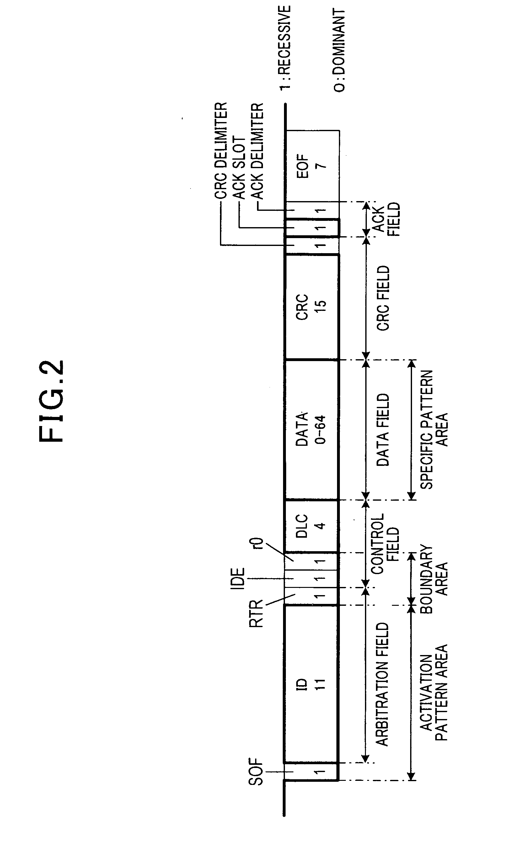
[0176]A portion (SOF and ID) of the activation pattern area of an activation frame is expressed by 11111(0)11111(0)1, where indicates SOF and (0) indicates a stuff bit. Thus, when ID=0x7FF is established, with a boundary condition being that an area having t...

third embodiment

[0229]With reference to FIGS. 20-23, hereinafter is described a third embodiment of the invention.

[0230]The present embodiment uses a data frame as an activation frame in which ID is set to 0x078. In other words, use of this ID is inhibited in the communication between the ECUs 10 whose operational mode is a normal mode.

[0231]The activation pattern area of the activation frame is expressed with bit patterns as: [0][0000(1)1111(0)00][0(1)00]. The first square brackets indicate SOF, the second square brackets indicate ID and the third square brackets indicate RTR, IDE and R0. Also, (0) and (1) indicate stuff bits.

[0232]This ID (=0x078) is a sole unique bit pattern in which each edge at which a receptive level turns to a dominant level is used as an edge of focus, and a bit length from the head (start timing) to the third edge of focus (end timing) is maximized (16 bits). From a different point of view, this ID is a sole unique bit pattern in which the number of edges of focus detected...


PUM


Abstract

In a communication system, plural nodes are communicably connected to a communication line and mutually communicate based on an NRZ (Non Return to Zero) code. Each node detects, as a data frame head, a dominant level when a signal on the line changes to a dominant level during a stand-by state of the line. An activation frame is transmitted during a sleep mode. The activation frame has an activation pattern area storing therein a bit pattern showing that the frame is the activation frame, a specific pattern area storing therein a bit pattern showing a node to be activated, a boundary position satisfying a predetermined boundary condition and being a boundary between the activation and specific pattern areas. Each node performs a switchover from the sleep mode to a normal mode based on the bit patterns in the activation and specific pattern areas and information given by the boundary position.

Description

CROSS-REFERENCE TO RELATED APPLICATION[0001]This application is based on and claims the benefit of priorities from earlier Japanese Patent Application Nos. 2010-196844, 2010-194664 and 2010-206792 filed Sep. 2, Aug. 31 and Sep. 15, 2010, respectively, the descriptions of which are incorporated herein by reference.BACKGROUND[0002]1. Technical Field[0003]The disclosure relates to a communication network configured by nodes having a sleep / wake-up function, and in particular to a technique for individually starting nodes which are in a sleep mode.[0004]2. Related Art[0005]It is known to use a protocol in an on-vehicle LAN to realize communication between a plurality of nodes installed in the vehicle.[0006]Among such on-vehicle LAN protocols, a protocol called CAN (Controller Area Network) is standardized (ISO11898-1).[0007]In CAN, “dominant” and “recessive” are defined as signal levels in a communication channel. When any one of nodes has outputted a signal having a dominant level, the ...

Claims


Application Information

Patent Timeline
Patent Type & Authority Applications(United States)
IPC IPC(8): H04L12/26H04J3/22
CPCH04L12/12H04L12/40039Y02B60/33H04L2012/40215Y02B60/34H04L41/0833Y02D30/50
Inventor MORI, HIROYUKISATAKE, MASAYOSHIKISHIGAMI, TOMOHISAMATSUOKA, TOSHIHIKO
Owner NIPPON SOKEN
Why Eureka
Try Eureka