
Driver architecture for computer device having multiple graphics subsystems, reduced power consumption modes, software and methods

a driver architecture and graphics subsystem technology, applied in static indicating devices, instruments, sustainable buildings, etc., can solve the problems of increasing overall power consumption, higher performance or additional capabilities, etc., and achieve the effect of reducing power consumption, consuming different amounts of electrical power, and consuming less power

Active Publication Date: 2009-06-18
ADVANCED MICRO DEVICES INC
View PDF16 Cites 86 Cited by
  • Summary
  • Abstract
  • Description
  • Claims
  • Application Information

AI Technical Summary

Benefits of technology

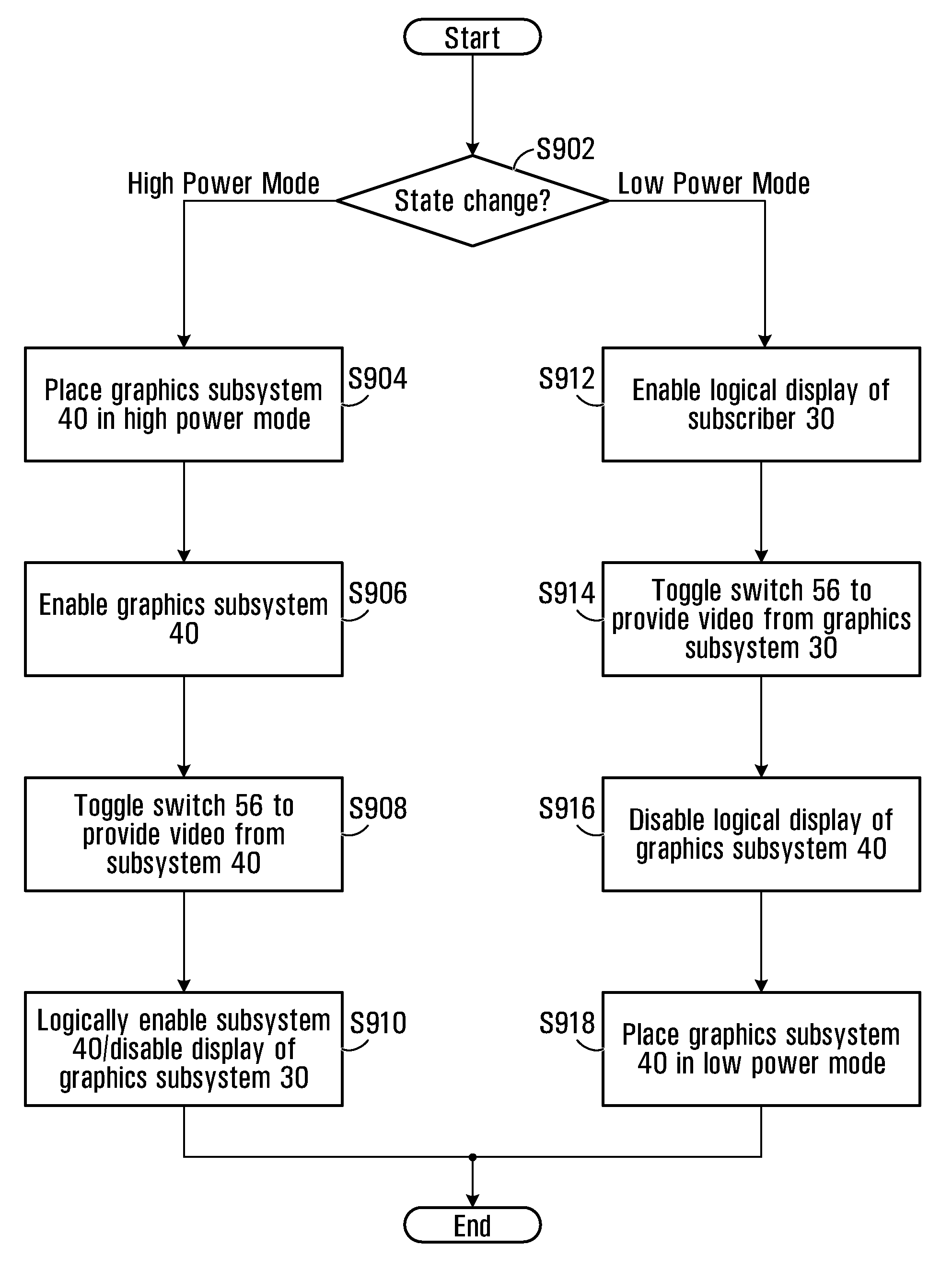
[0010]Many computing device may now include two or more graphics subsystems. The multiple graphics subsystems may have different abilities, and may, for example, consume differing amount of electrical power, with one subsystem consuming more average power than the others. The higher power consuming graphics subsystem may be coupled to the device and used instead of, or in addition to, the lower power consuming graphics subsystem, resulting in higher performance or additional capabilities, but increased overall power consumption. By transitioning from the use of the higher power consuming graphics subsystem to the lower power consuming graphics subsystem, while placing the higher power consuming graphics subsystem in a lower power consumption mode, overall power consumption is reduced.

Problems solved by technology

The higher power consuming graphics subsystem may be coupled to the device and used instead of, or in addition to, the lower power consuming graphics subsystem, resulting in higher performance or additional capabilities, but increased overall power consumption.

Method used


Image

  • Driver architecture for computer device having multiple graphics subsystems, reduced power consumption modes, software and methods
  • Driver architecture for computer device having multiple graphics subsystems, reduced power consumption modes, software and methods
  • Driver architecture for computer device having multiple graphics subsystems, reduced power consumption modes, software and methods

Examples


Embodiment Construction

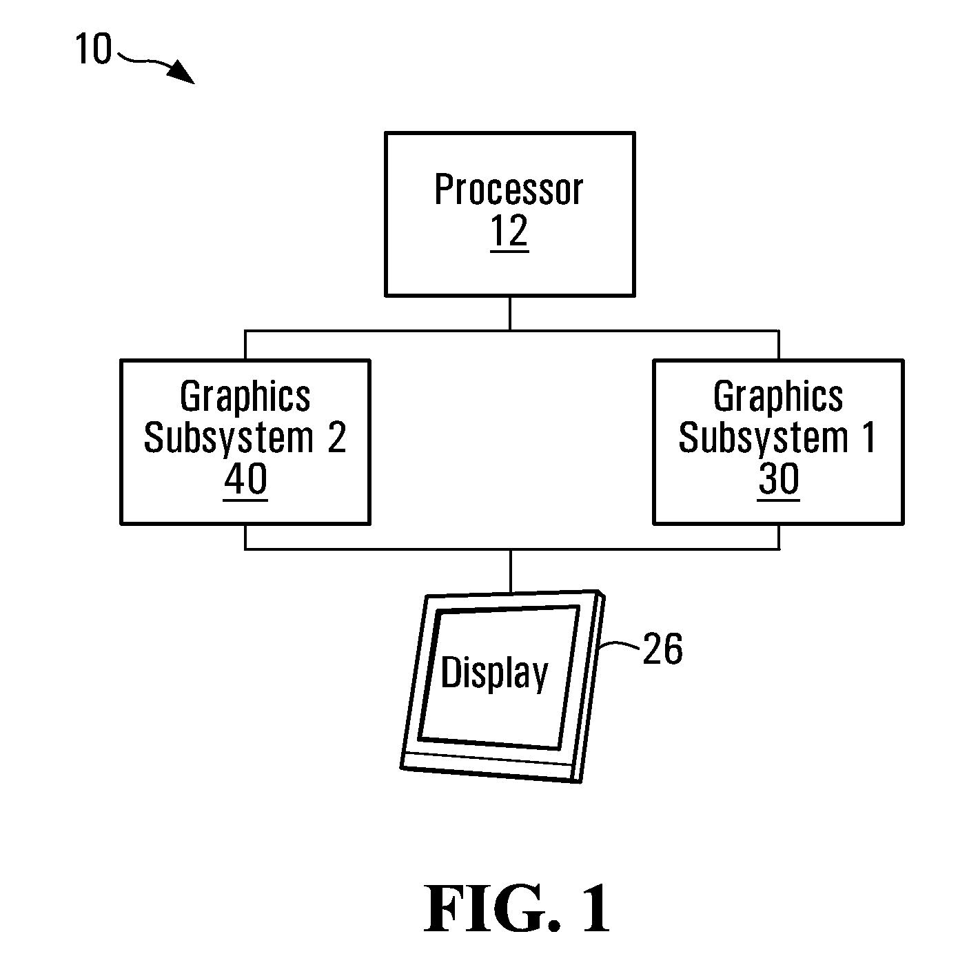
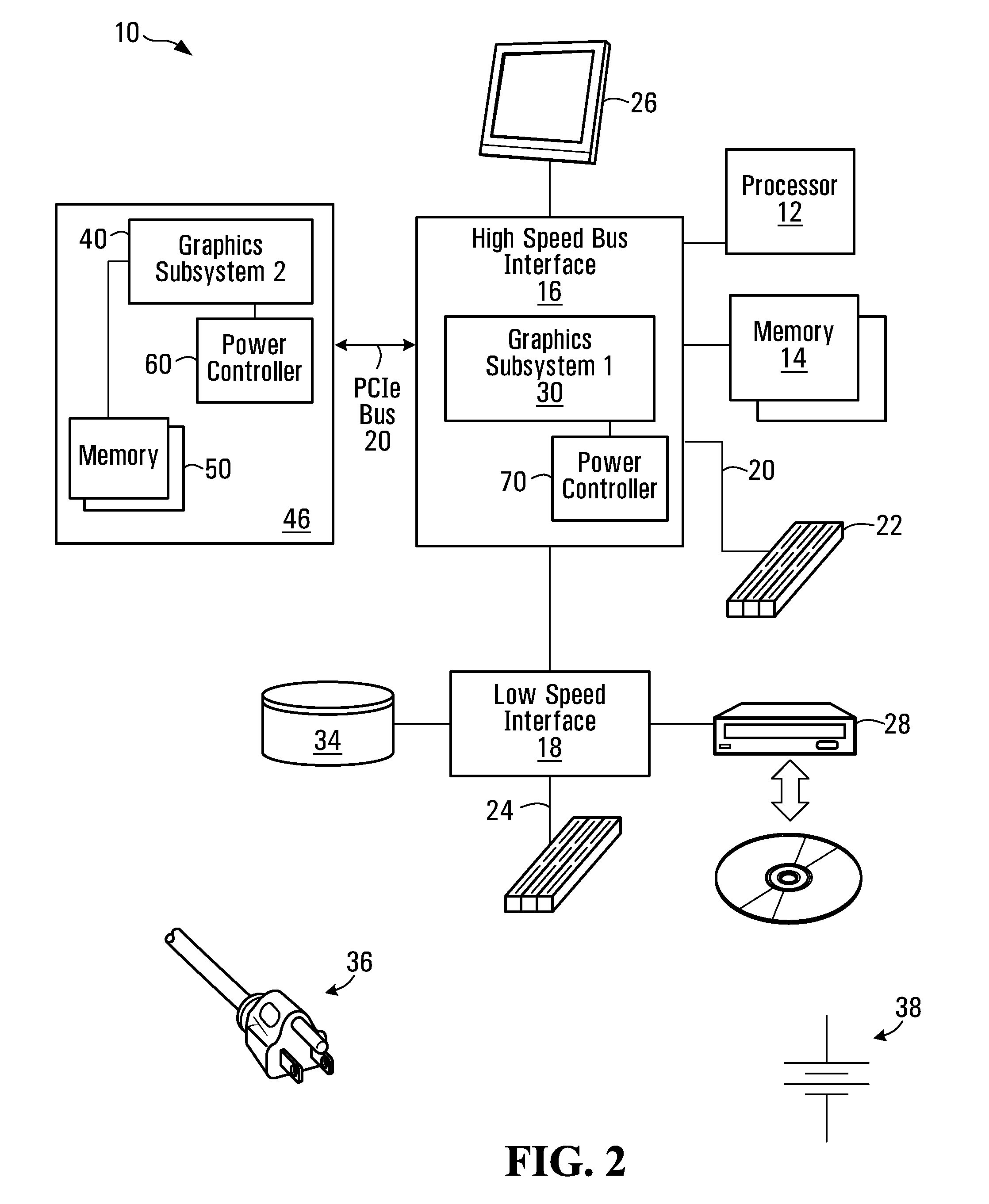
[0031]FIG. 1 is a simplified, high level, block diagram of an electronic device 10, including two graphics subsystems 30 and 40 and a display 26. As will become apparent, each graphics subsystem30, 40 includes specialized electronic circuits capable of rendering computer graphics, in the form of one or more of 2D graphics, 3D graphics, decoded motion video or the like.

[0032]One graphics subsystem 40 may consume higher average power than the other graphics subsystem 30. Typically, graphics subsystem 40 consumes the higher average power has greater graphics rendering capability than graphics subsystem 30. Graphics subsystem 40 may, for example, be able to render 2D or 3D graphics at a higher frame rate than the graphics subsystem that consumes the lower average power. Similarly, graphics subsystems 30, 40 need not have identical capabilities. Graphics subsystem 40 typically includes more functional blocks than graphics subsystem 30.

[0033]Both graphics subsystem 30 and 40 may be physic...


PUM


Abstract

Many computing device may now include two or more graphics subsystems. The multiple graphics subsystems may have different abilities, and may, for example, consume differing amount of electrical power, with one subsystem consuming more average power than the others. The higher power consuming graphics subsystem may be coupled to the device and used instead of, or in addition to, the lower power consuming graphics subsystem, resulting in higher performance or additional capabilities, but increased overall power consumption. By transitioning from the use of the higher power consuming graphics subsystem to the lower power consuming graphics subsystem, while placing the higher power consuming graphics subsystem in a lower power consumption mode, overall power consumption is reduced. A processor executes application software and driver software. The driver software includes first and second driver components for respectively controlling operation of the first and second graphics subsystems. A further proxy driver component routes calls (e.g. API / DDI calls) to one of said first and second driver components, in dependence on which of the first and second graphics system is in use.

Description

CROSS-REFERENCE TO RELATED APPLICATIONS[0001]This application claims the benefit of U.S. Provisional Application Ser. No. 61 / 013,527 filed Dec. 13, 2007, entitled “DRIVER ARCHITECTURE FOR COMPUTING DEVICE HAVING MULTIPLE GRAPHICS SUBSYSTEMS, REDUCED POWER CONSUMPTION MODES, SOFTWARE AND METHODS”, having as an inventors Phil Mummah and Paul Blinzer, and owned by instant assignee and hereby incorporated by reference in its entirety. This application is also related to U.S. patent application Ser. No. 11 / 421,005 filed May 30, 2006, and U.S. patent application Ser. No. 11 / 755,625, filed May 30, 2007, the contents of both of which are hereby incorporated by reference.FIELD OF THE INVENTION[0002]The present invention relates generally to computing devices, and more particularly to devices having multiple graphics subsystem, and the associated software drivers. As well, in one aspect, the invention is directed to methods for lowering the power consumption in such devices.BACKGROUND OF THE ...

Claims


Application Information

Patent Timeline
Patent Type & Authority Applications(United States)
IPC IPC(8): G06F3/038G06F15/16
CPCG06F1/3203G06F1/3265G06F1/3293G09G5/12G09G5/363G09G2360/06G09G2340/0435G09G2370/04Y02B60/121Y02B60/1242G09G2330/022Y02D10/00
Inventor BLINZER, PAULMUMMAH, PHIL
Owner ADVANCED MICRO DEVICES INC
Learn More