This helps you quickly interpret patents by identifying the three key elements:
Problems solved by technology
Method used
Benefits of technology
Benefits of technology
[0013]With the present constitution, group master rotation timing can be accurately detected based on communication traffic volume, which has a high correlation with wireless node power consumption.
[0040]With the present constitution, if there is a wireless node having an extremely serious bit error rate even after intra-group group master rotation, merging of groups, or inter-group wireless node exchange, such wireless node is forcibly separated from the group, thereby avoiding network problems caused by wireless node malfunction due to power exhaustion.
Problems solved by technology
However, with this method, because processes are concentrated in a single master unit, and the traffic volume of transmission / reception in the master unit is exceedingly large compared to the slave units, if there is shortage in the remaining power of a battery serving as a power source for the master unit, problems occur such as slowdown of the entire network due to master unit transmission / reception output shortage, or at worst, disconnection of the communication circuit due to master unit battery rundown.
This leads to the problem that the effect of eliminating imbalances in power consumption by having slave units with excess battery power switch to serve as an actual master unit is not fully and efficiently demonstrated.
Further, because in such a constitution an actual master unit is selected from among all the slave units, in a case where wireless nodes are distributed across a wide range, the average wireless communication distance between the actual master unit and slave units becomes longer and the power consumption for the entire network required for wireless transmission increases, so that on average any wireless node is likely to experience battery rundown at an early stage.
Further, in a case where a slave unit is outside the radio wave range given the transmission power of the selected actual master unit, such slave unit needs to be separated from the network even when it has sufficient battery power, or the actual master unit and slave units need to be physically moved each time to a location where reception can be obtained, resulting in the problem of considerably degraded network performance and convenience.
Method used
Image
Click on the blue label to locate the original text in one second.
Reading with bidirectional positioning of images and text.
Examples
first embodiment
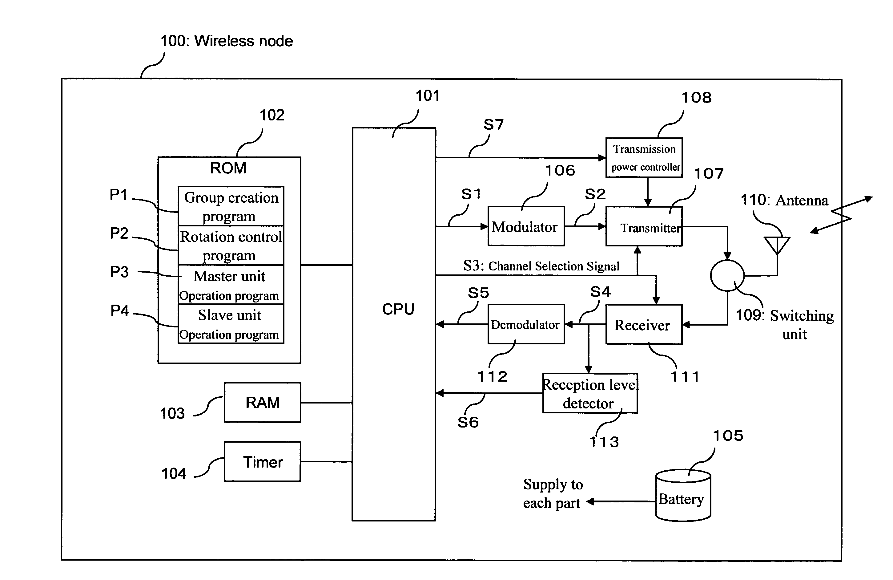
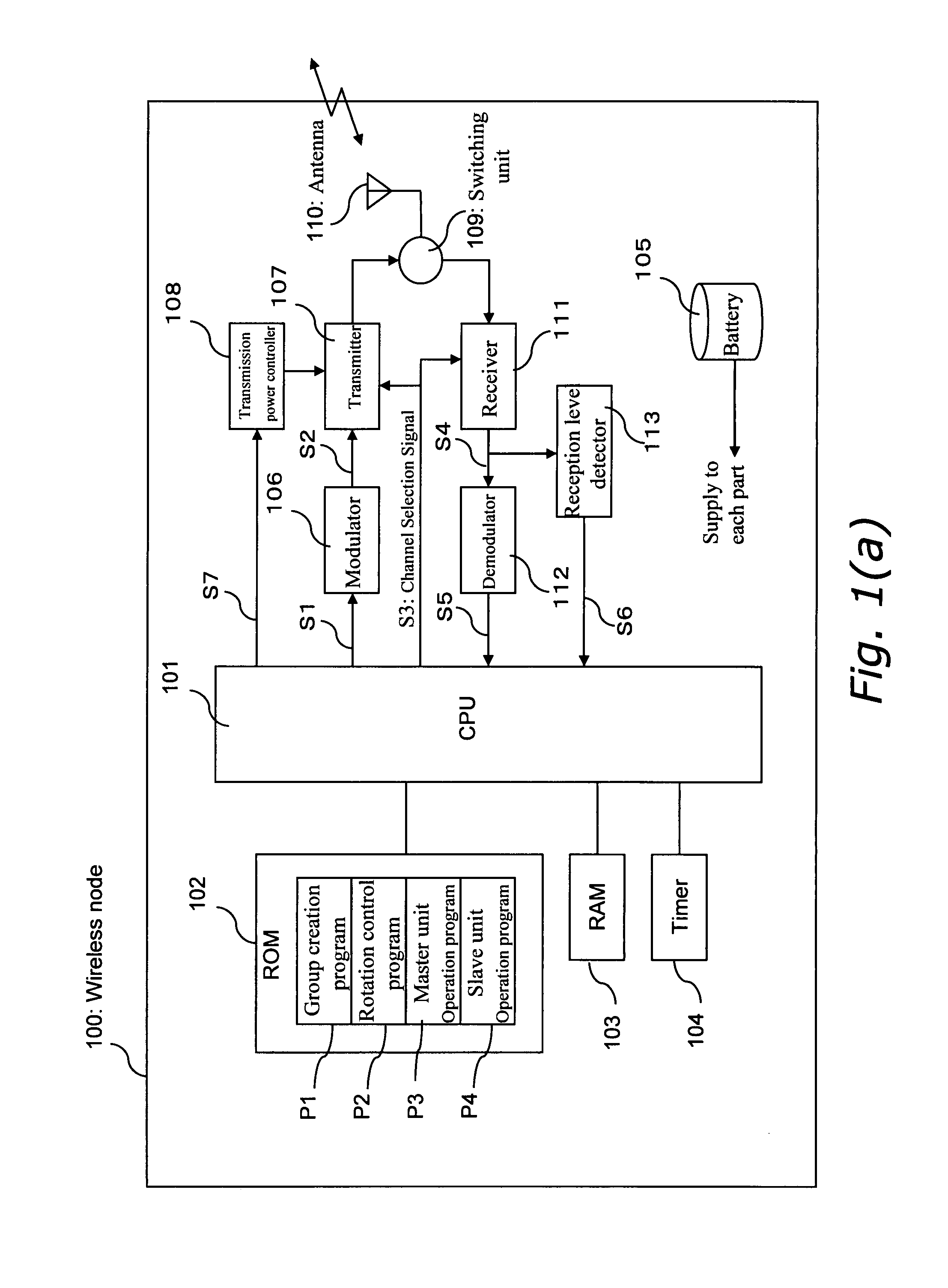
[0073]FIG. 1 (a) is a block diagram of a wireless node in the first embodiment of the present invention.
[0074]In FIG. 1 (a), a wireless node 100 comprises a CPU 101 for controlling the various units of the wireless node and processing transmission / reception data, a ROM 102 having programs stored therein, a RAM 103, a timer 104, a battery 105 for supplying power to each unit of the wireless node including the CPU 101, a modulator 106, a transmitter 107, a transmission power controller 108, a switching unit 109 for performing switching between transmission radio waves and reception radio waves, an antenna 110, a receiver 111, a demodulator 112, and a reception level detector 113.
[0075]When the wireless node 100 is to perform transmission, it does so as follows. The CPU 101 executes the necessary programs from among a group of programs included in the ROM 102 while using the RAM 103 as working memory, and creates transmission data S1. The transmission data S1 is modulated by the modula...
second embodiment
[0120]FIG. 7 is a flowchart for explaining a group master rotation operation using communication traffic in a second embodiment of the present invention.
[0121]In FIG. 7, a group master node sets in advance a rotation traffic volume that is to serve as a criterion for determining time for group master node rotation (Step 701), receives slot data, and accumulates for each slave node the volume of communication traffic with such slave node (Step 702). When it has received data from all slots, it checks whether the volume of communication traffic with the slave nodes has reached the rotation traffic volume set in Step 701 (Step 703). If the communication traffic volume has not reached the rotation traffic volume, slot data reception is continued, and if the communication traffic volume of any one of the slave nodes has reached the rotation traffic volume, a rotation control program is started (Step 704). At this time, because it is assumed that the slave node having the least traffic vo...
third embodiment
[0126]FIG. 8 is a block diagram of a wireless node in the third embodiment of the present invention.
[0127]In FIG. 8, the same constitutional elements as in FIG. 1 (a) are assigned the same reference numerals, and explanation thereof is omitted.
[0128]In FIG. 8, a wireless node 800 comprises a battery power detector 801. The battery power detector 801 is configured to detect the amount of remaining power based on voltage and the like of a battery 105, and to input the battery power level S8 into the CPU 101. With such a configuration, the CPU 101 is capable of checking remaining battery power.
[0129]An explanation will be given with reference to the flowchart in FIG. 9 for the process of group master node rotation, using the wireless node 800 thus configured and based on remaining battery power.
[0130]FIG. 9 is a flowchart for explaining a group master rotation operation using remaining battery power in the third embodiment of the present invention.
[0131]In FIG. 9, a slave node checks r...
PUM
Abstract
The invention comprises a step of constructing a plurality of groups using a plurality of wireless nodes during construction of a network; a step of provisionally deciding, from among the wireless nodes in each group, a group master node serving as a group master that communicates with the other nodes in the group and that functions as a communication relaystation for communicating with the other groups, with the other nodes in the group serving as slave nodes that are connected under the control of the group master node to perform their respective terminal station operation; a step in which the wireless nodes in each group exchange data with each other at a commencement session and calculate the minimum required transmission power for each other; a step in which the wireless nodes in each group use the calculated minimum required transmission powers to communicate with each other; and a step of, when determining that the time of changing the group master has come, causing one of the slave nodes to take over the group master.
Description
TECHNICAL FIELD[0001]The present invention relates to an interactive wireless communication network system comprising a plurality of wireless nodes (wireless transmitters / receivers); more particularly, it relates to a power management method for managing power consumption of battery-driven wireless nodes, and a network system therefor.BACKGROUND ART[0002]An interactive wireless communication network system includes a host unit for collecting information and a plurality of wireless nodes, and the wireless nodes in particular comprise a master unit for performing overall network processing among a group of wireless nodes, and a plurality of slave units dependent thereupon. With such a wireless node configuration, the master unit establishes an ad-hoc network with each slave unit as necessary to perform interactive wireless communication with each slave unit, and performs interactive communication with the host unit representing the wireless node group. Thus, the master unit collects i...
Claims
Application Information
Patent Timeline
Application Date:The date an application was filed.
Publication Date:The date a patent or application was officially published.
First Publication Date:The earliest publication date of a patent with the same application number.
Issue Date:Publication date of the patent grant document.
PCT Entry Date:The Entry date of PCT National Phase.
Estimated Expiry Date:The statutory expiry date of a patent right according to the Patent Law, and it is the longest term of protection that the patent right can achieve without the termination of the patent right due to other reasons(Term extension factor has been taken into account ).
Invalid Date:Actual expiry date is based on effective date or publication date of legal transaction data of invalid patent.

