

Broadband proximity-coupled cavity backed patch antenna
- Summary
- Abstract
- Description
- Claims
- Application Information
AI Technical Summary
Benefits of technology
Problems solved by technology
Method used
Image

Examples
Embodiment Construction
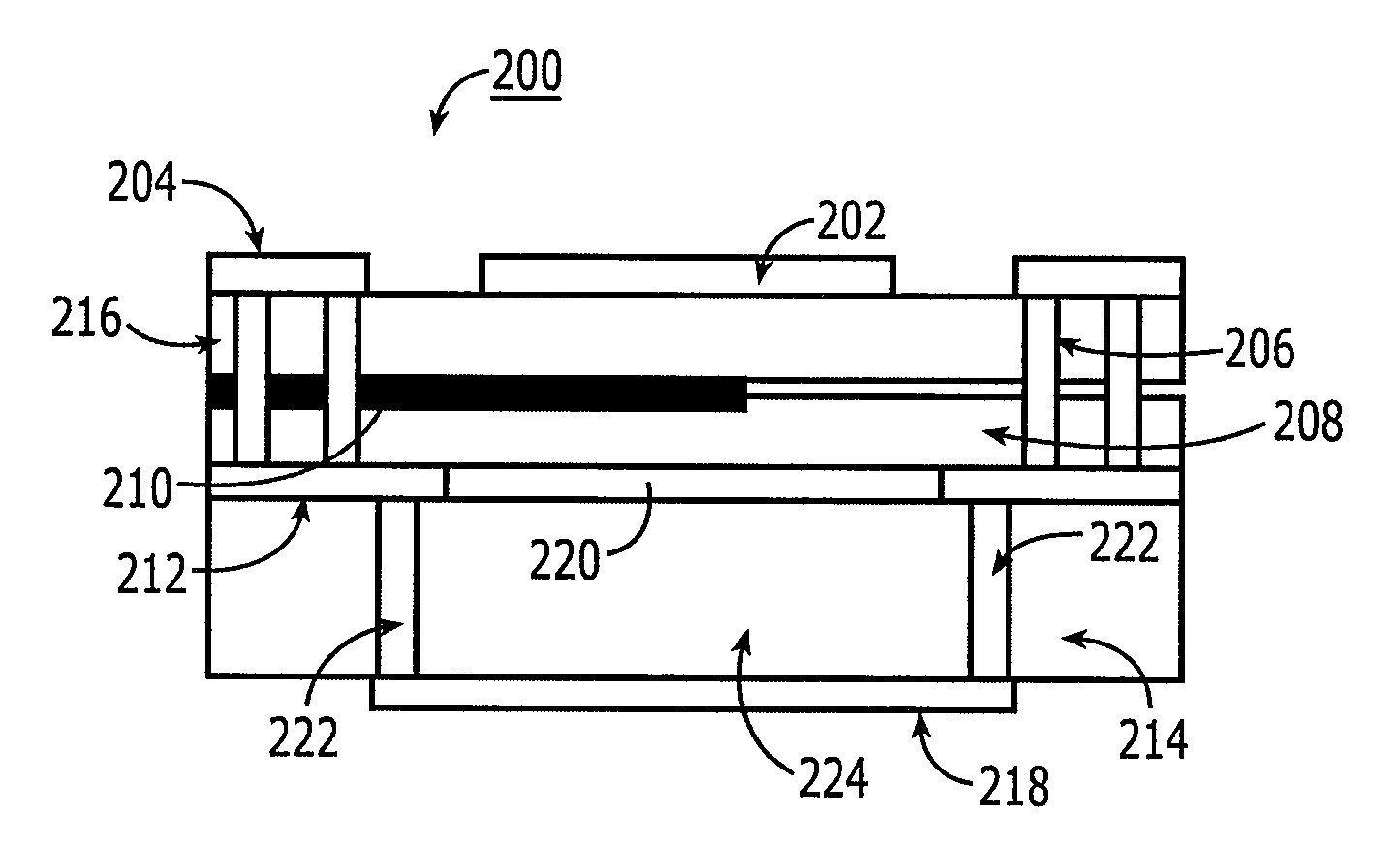
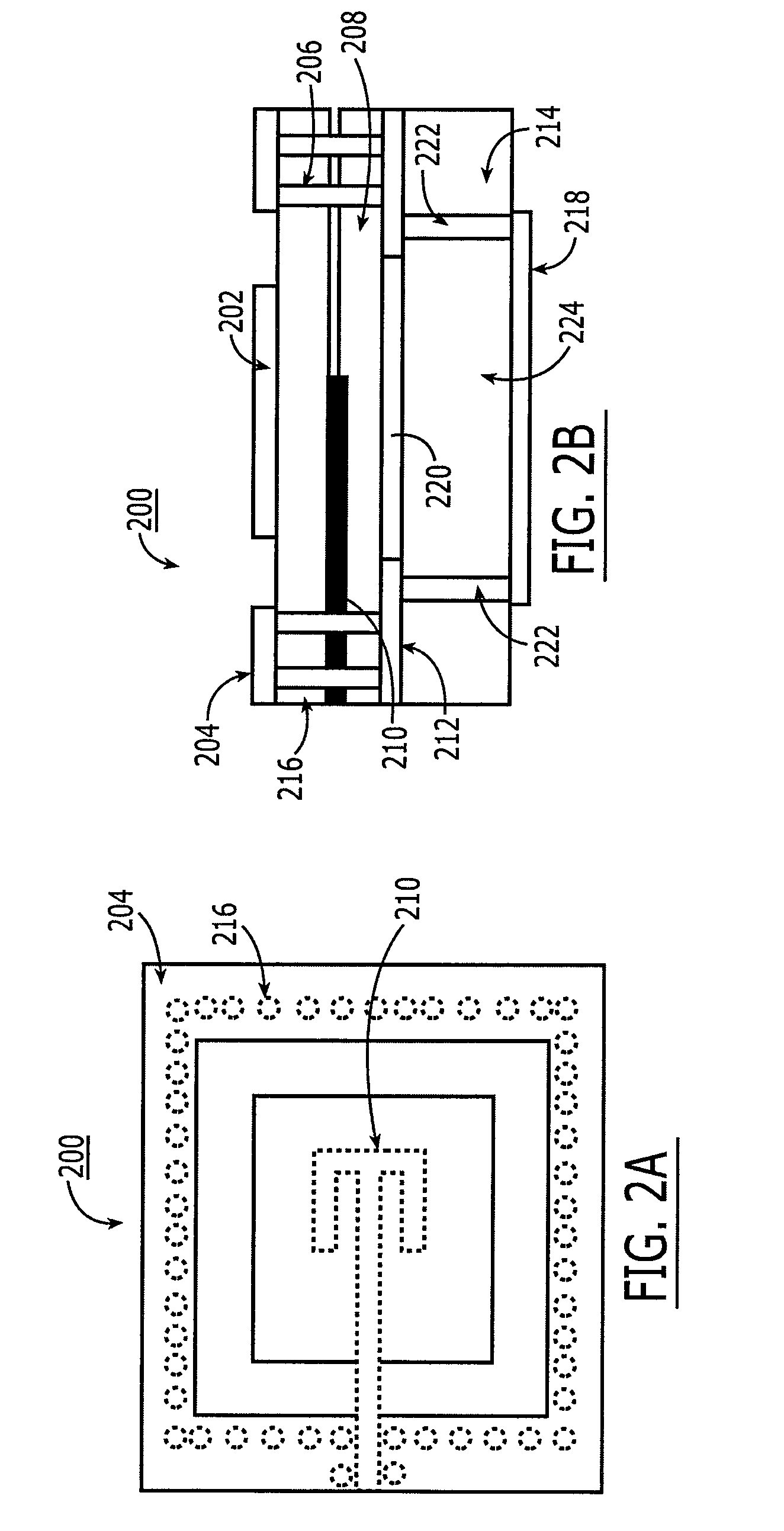
[0032]FIGS. 2A and 2B are top plan and cross-sectional side views, respectively, of a proximity-coupled cavity-backed patch antenna 200 in accordance with a first embodiment of the present invention. The antenna patch 202 is disposed on top of a thin substrate 206. It is peripherally surrounded by a top ground plane 204.
[0033] Substrate 206 may be any low loss substrate material conventionally used by those of skill in the art for constructing patch antennas, such as RT Duroid®, or a Teflon-based substrate, such as manufactured by Rogers, Taconics and Arlon. It also could be very thin flexible substrate (normally known as Flex). Such substrates typically have a permittivity of about 2 to about 4.
[0034] Disposed on the top side of a second, thin substrate 208 and / or on the underside of the first substrate 206 is a feed line 210. The feed line 210 may be a microstrip or a strip line. A middle ground plane 212 is disposed on the bottom side of the second substrate 208. The middle gro...
PUM
 Abstract
Description
Claims
Application Information