
RF(Radio frequency) information stealing detecting terminal

A terminal and secret stealing technology, applied in the field of RF secret stealing detection terminals, can solve problems such as inability to distinguish, no solution proposed, unable to detect signal strength, etc., to achieve the effect of widening bandwidth, refinement and accurate detection

Active Publication Date: 2017-09-12
北京中密安信息安全技术有限公司
View PDF6 Cites 2 Cited by
  • Summary
  • Abstract
  • Description
  • Claims
  • Application Information

AI Technical Summary

Problems solved by technology

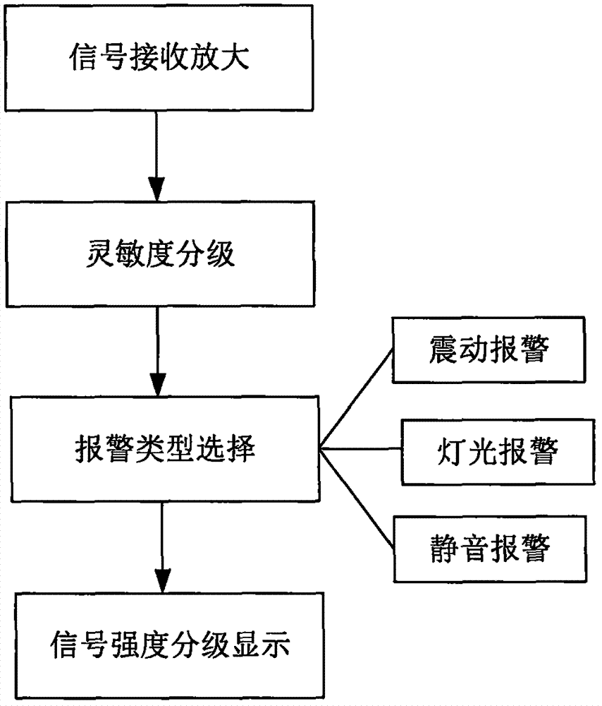
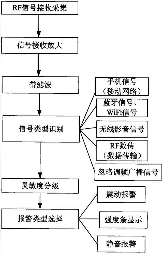
[0006] At present, detectors that can detect mobile phone uplink signals can only distinguish between 2G signals and 3G signals, and need to be within 1 meter from the signal source (and need to be in a call), and for each type of mobile phone signal, It is also impossible to specifically distinguish which type of network signal it is (for example, when a 2G mobile network signal is detected, it cannot distinguish whether the signal is a CDAM network signal or a GSM network signal), let alone detect the signal strength
[0007] For the uplink signal of the public frequency band, the current wireless detector can only detect and identify the 2.4G signal, but it cannot distinguish whether the 2.4G signal is a WIFI or Bluetooth signal, or a wireless audio-visual signal; it cannot recognize 5.8G Correspondingly, it is impossible to judge whether the signal type of the 5.8G signal is a wireless audio-visual signal or a WIFI network; at the same time, it cannot identify the 1.2G wireless audio-visual signal
[0008] For the above-mentioned problems in related technologies, no effective solution has been proposed yet

Method used


Image

  • RF(Radio frequency) information stealing detecting terminal
  • RF(Radio frequency) information stealing detecting terminal
  • RF(Radio frequency) information stealing detecting terminal

Examples


Embodiment Construction

[0039] The following will clearly and completely describe the technical solutions in the embodiments of the present invention with reference to the accompanying drawings in the embodiments of the present invention. Obviously, the described embodiments are only some, not all, embodiments of the present invention. All other embodiments obtained by persons of ordinary skill in the art based on the embodiments of the present invention belong to the protection scope of the present invention.

[0040] According to an embodiment of the present invention, an RF stealth detection terminal is provided.

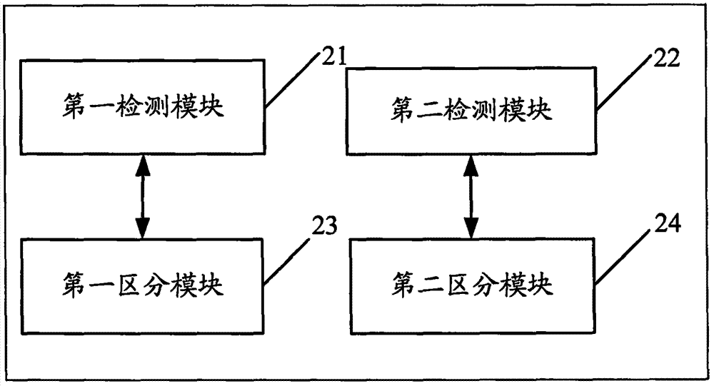
[0041] Such as figure 2 As shown, the RF stealth detection terminal according to the embodiment of the present invention includes:

[0042] The first detection module 21 is used to detect the uplink signal of the public frequency band of the stealing device;

[0043] The second detection module 22 is used to detect the uplink signal of the mobile network of the stealing device;

[0...


PUM


Abstract

The invention discloses an RF(Radio Frequency) information stealing detecting terminal. The RF information stealing detecting terminal comprises a first detecting module, a second detecting module and a first distinguishing module, wherein the first detecting module is used for detecting an up-link signal of a public frequency band of information stealing equipment; the second detecting module is used for detecting an up-link signal of a mobile network of the information stealing equipment; and the first distinguishing module is used for distinguishing the type of the public frequency band signal according to a modulation manner of the public frequency band signal under the situation that the public frequency band signal is detected by the first detecting module. According to the RF information stealing detecting terminal disclosed by the invention, the public frequency band signal and the mobile network signal are separately detected, so that the bandwidth of a detected frequency band is widened; and according to the modulation manner, the detected public frequency band signal is distinguished, so that detection of the uplink public frequency band signal of the information stealing equipment is refined and accurate.

Description

technical field [0001] The present invention relates to the technical field of communications, in particular to an RF (Radio Frequency, radio frequency) stealth detection terminal. Background technique [0002] At the beginning of the 19th century, countries around the world began to use analog wireless stealing technology to steal state secrets and military secrets. With the development of science and technology, secret-stealing technology continues to mature, and secret-stealing equipment is also in various forms, and is gradually developing towards miniaturization and automation. At the same time, anti-theft technology has also emerged as the times require. Through technical means and testing instruments, wireless theft is detected and discovered to meet the needs of preventing theft and keeping secrets. The earliest is a manual mediation receiving directional detection instrument. The field strength detection technology was used in the 1970s, and the frequency sweep tec...

Claims


Application Information

Patent Timeline
IPC IPC(8): H04W24/00H04B17/318
CPCH04B17/318H04W24/00
Inventor 康清军
Owner 北京中密安信息安全技术有限公司
Learn More