Power supply apparatus for power amplifier

Active Publication Date: 2017-01-19
SAMSUNG ELECTRO MECHANICS CO LTD +1
View PDF25 Cites 4 Cited by
  • Summary
  • Abstract
  • Description
  • Claims
  • Application Information

AI Technical Summary

Benefits of technology

[0027]The method may further include inserting a high frequency zero signal, in a compensato

Problems solved by technology

However, when power amplifiers are generally designed, there exists a disadvantage in that the power amplifier is reduced from a maximum power point by several dB, in order to secure linearity.
This results in the reduction of overall efficiency of the system because efficiency is decreased at lowe

Method used


Image

  • Power supply apparatus for power amplifier
  • Power supply apparatus for power amplifier
  • Power supply apparatus for power amplifier

Examples


Example

[0039]Throughout the drawings and the detailed description, the same reference numerals refer to the same elements. The drawings may not be to scale, and the relative size, proportions, and depiction of elements in the drawings may be exaggerated for clarity, illustration, and convenience.

DETAILED DESCRIPTION

[0040]The following detailed description is provided to assist the reader in gaining a comprehensive understanding of the methods, apparatuses, and / or systems described herein. However, various changes, modifications, and equivalents of the methods, apparatuses, and / or systems described herein will be apparent to one of ordinary skill in the art. The sequences of operations described herein are merely examples, and are not limited to those set forth herein, but may be changed as will be apparent to one of ordinary skill in the art, with the exception of operations necessarily occurring in a certain order. Also, descriptions of functions and constructions that are well known to o...


PUM


Abstract

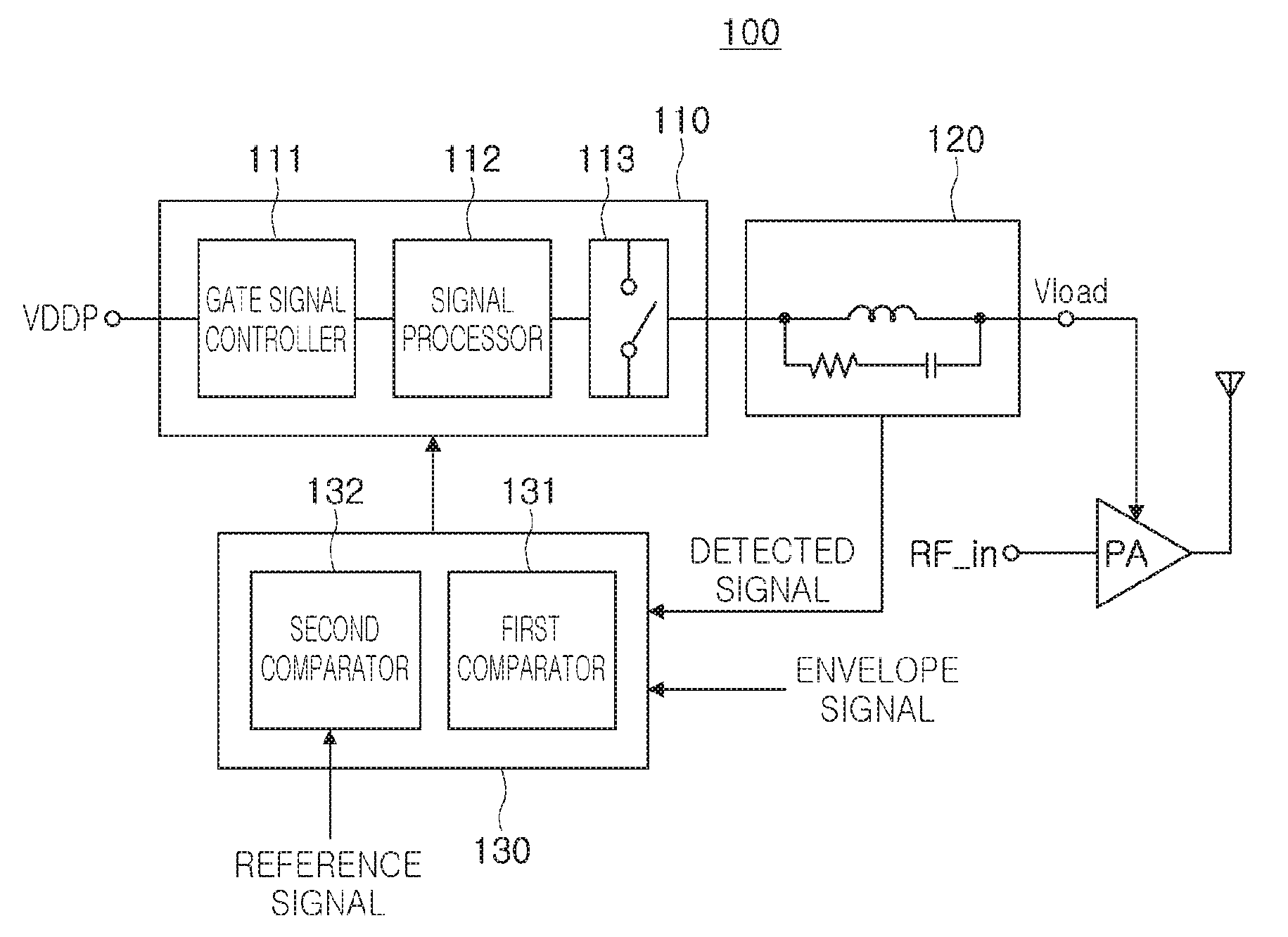
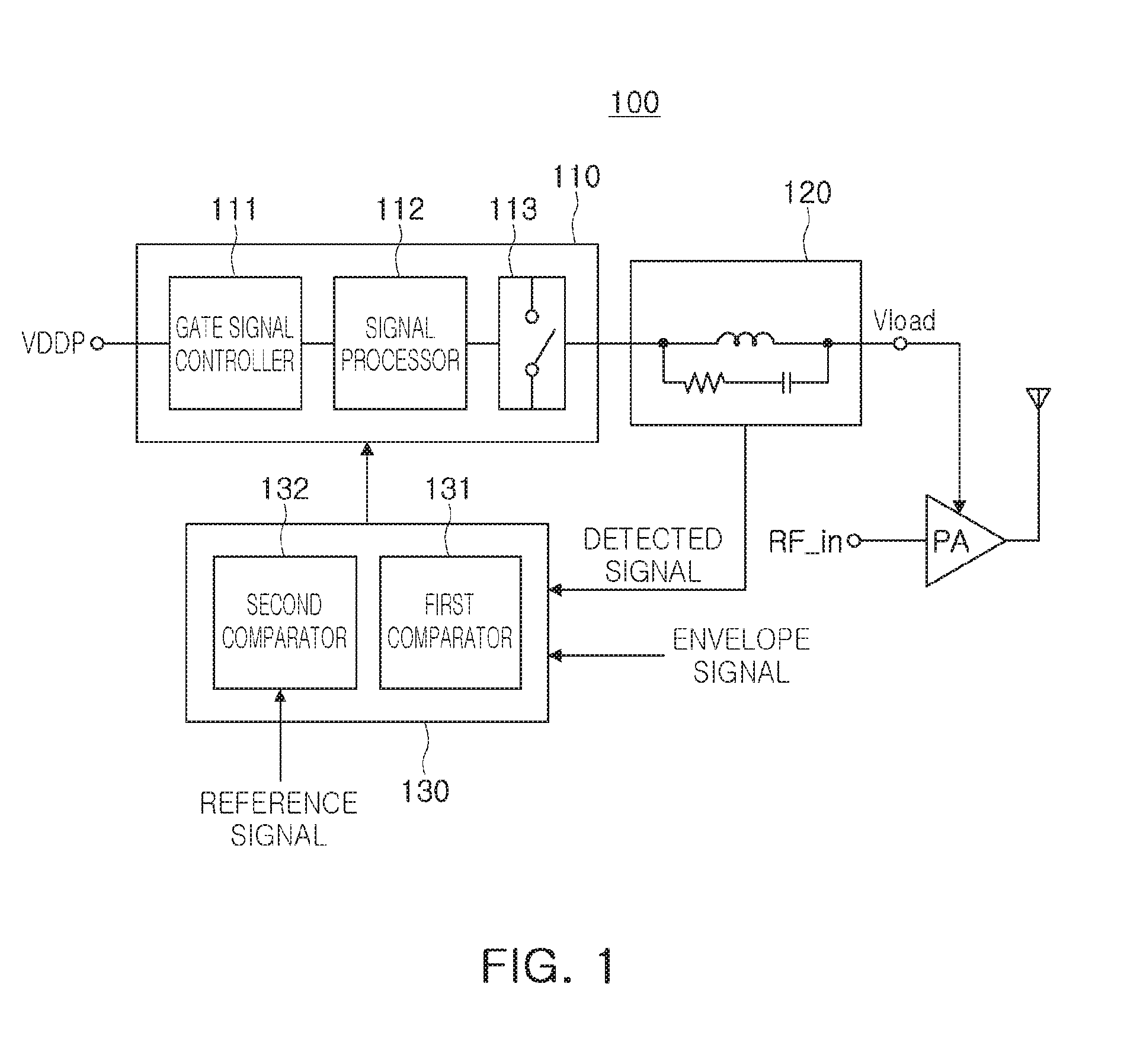
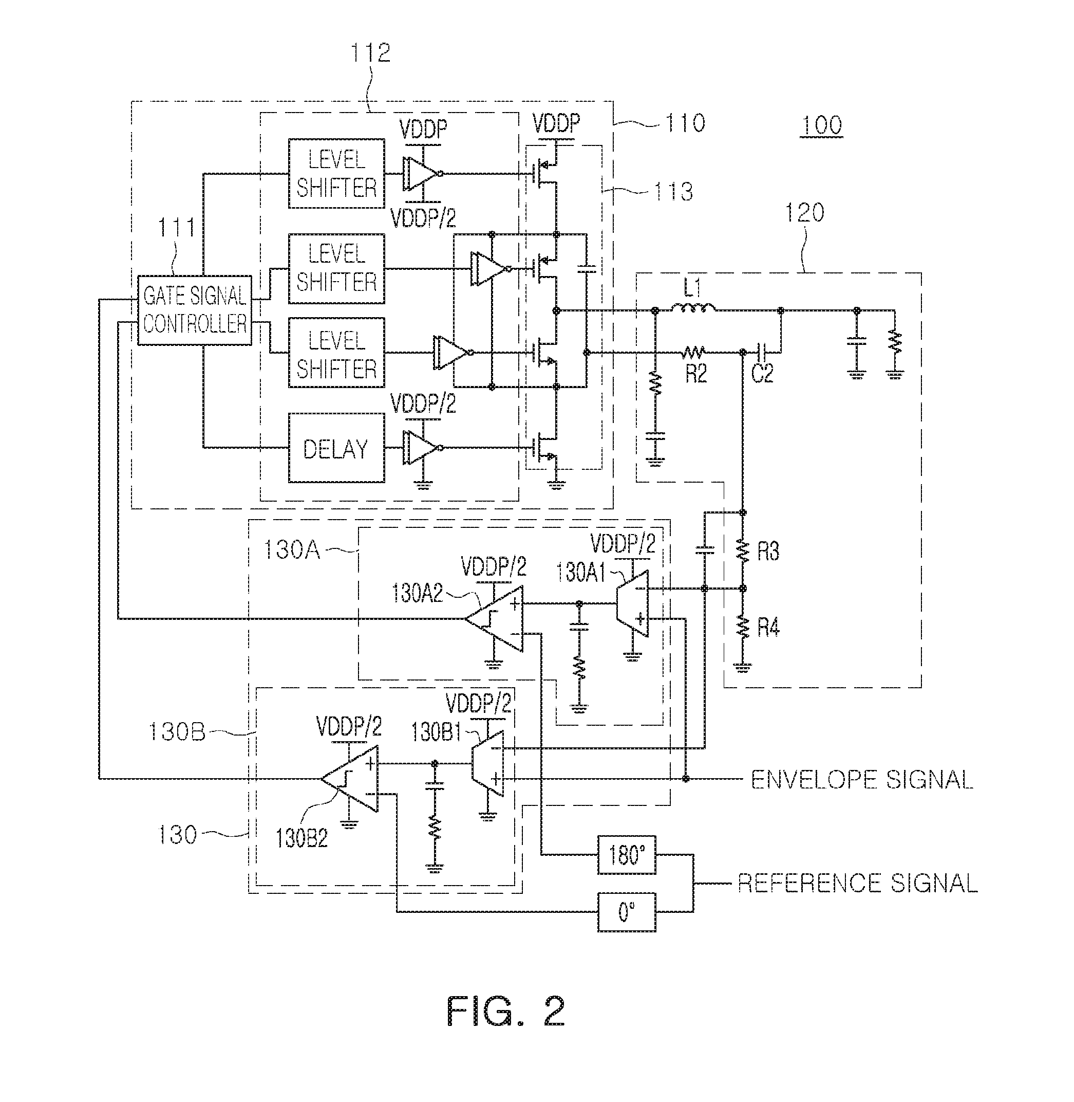
A power supply apparatus for a power amplifier includes a converter configured to convert input power into driving power for the power amplifier, a detector configured to transfer the driving power from the converter to the power amplifier, including an inductor formed on a detection path of the driving power, and configured to detect power information regarding the driving power to generate a detected signal, and a controller configured to control power conversion of the converter based on an envelope signal of a signal input to the power amplifier and the detected signal.

Description

CROSS-REFERENCE TO RELATED APPLICATION(S)[0001]This application claims the benefit under 35 U.S.C. §119(a) of Korean Patent Application No. 10-2015-0100009 filed on Jul. 14, 2015,in the Korean Intellectual Property Office, the entire disclosure of which is incorporated herein by reference for all purposes.BACKGROUND[0002]1. Field[0003]The following description relates to a power supply apparatus supplying power to a power amplifier used for wireless communications.[0004]2. Description of Related Art[0005]Wireless communications schemes allowing large amounts of information to be transmitted have recently become more commonplace. The characteristics of wireless transmission signals currently used in wireless communications and intended for use in the future have a wide band and a high peak to average power ratio.[0006]Accordingly, signal bandwidths are increased. In order to improve overall efficiency of systems in such environments, the consumption of direct current power by power a...

Claims


Application Information

Patent Timeline
IPC IPC(8): H04B1/04H02M1/08H03F3/21H03F3/19H03G3/00H03F1/02
CPCH04B1/0475H03G3/007H03F1/0211H03F3/21H03F2200/105H02M1/08H03F2200/451H04B2001/0416H03F3/19H03F3/20H02M1/0003H02M3/158H02M3/1584H03F3/245H03F2200/102H02M1/0025H02M1/0095H02M7/4837
Inventor GWON, HUI DONGCHO, GYU HYEONGKIM, JEONG HOON
Owner SAMSUNG ELECTRO MECHANICS CO LTD
Why Eureka
Try Eureka