Shield connector structure

a shield connector and connector technology, applied in the direction of coupling device connection, coupling protective earth/shielding arrangement, electrical equipment, etc., can solve the problems of electric noise leakage to the outside, noise flow, and electric noise cannot be sufficiently discharged, so as to achieve satisfactory shield performance, effective discharge of noise, and satisfactory shield performance

Inactive Publication Date: 2010-07-13
YAZAKI CORP
View PDF7 Cites 16 Cited by
  • Summary
  • Abstract
  • Description
  • Claims
  • Application Information

AI Technical Summary

Benefits of technology

[0010]The present invention aims to solve the above-described problems. That is, an object of the invention is to provide a shield connector structure capable of exhibiting a more satisfactory shield performance by shortening a path, through which a return current flows, so as to effectively discharge noise.

Problems solved by technology

However, since a power having a high voltage is supplied to this kind of driving motor, a problem arises in that electric noise leaks to the outside from a terminal metal part of a connector used to supply a power to the above-described motor or electric noise flows from the terminal metal part to another terminal metal part.
However, since a part of the above-described electric noise flows from the shield shell of the opposed shield connector to the outer shield shell via the inner shield shell of the shield connector so as to be discharged to the outside, a path from the shield shell to the outer shield shell becomes long, and a return current cannot flow due to an electric resistance in the path, thereby causing a problem in that electric noise cannot be sufficiently discharged.

Method used


Image

  • Shield connector structure
  • Shield connector structure
  • Shield connector structure

Examples


second embodiment

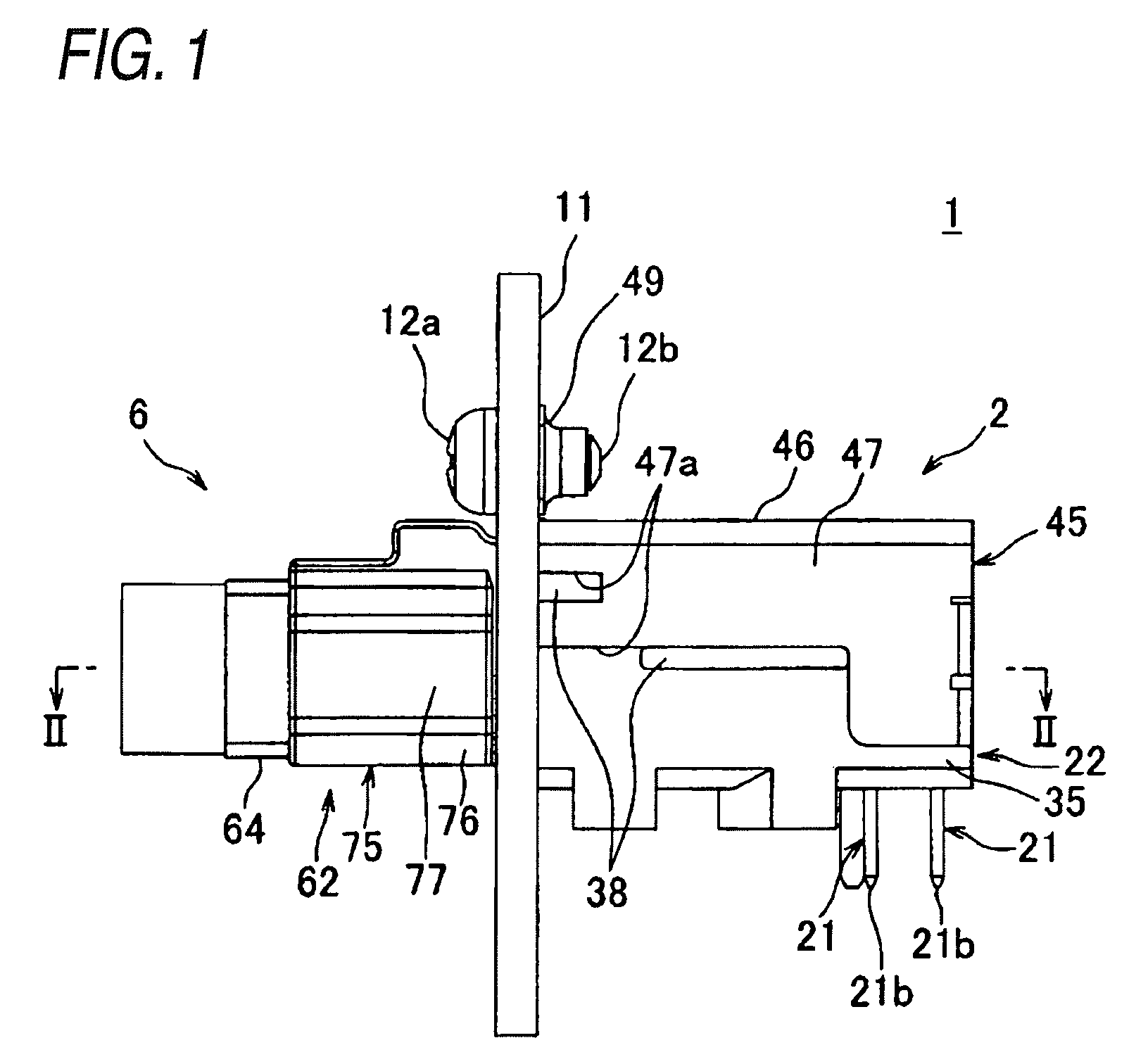
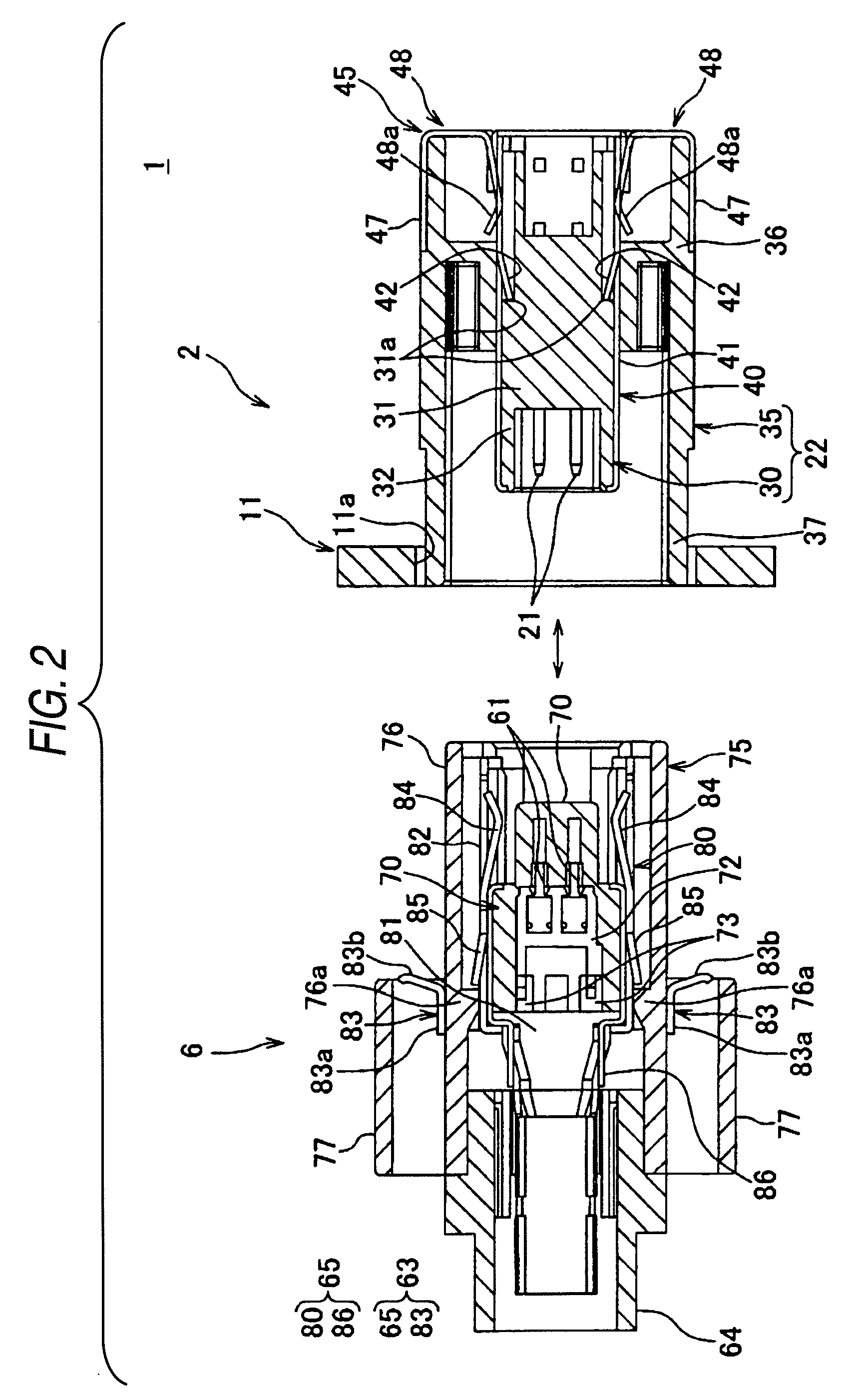
[0099]As shown in FIG. 8 and the like, the shield connector structure according to the invention includes the pair of connectors 2 and 6 which has the shield shells 23 (shown in FIG. 14) and 63 (shown in FIG. 10) and is capable of being fitted to each other; and the conductive connector attachment portion 11 which contacts one shield shell 23 so as to ground the shield shell 23. When the connectors 2 and 6 are fitted to each other, the shield shells 23 and 63 are shield-connected to each other.

first embodiment

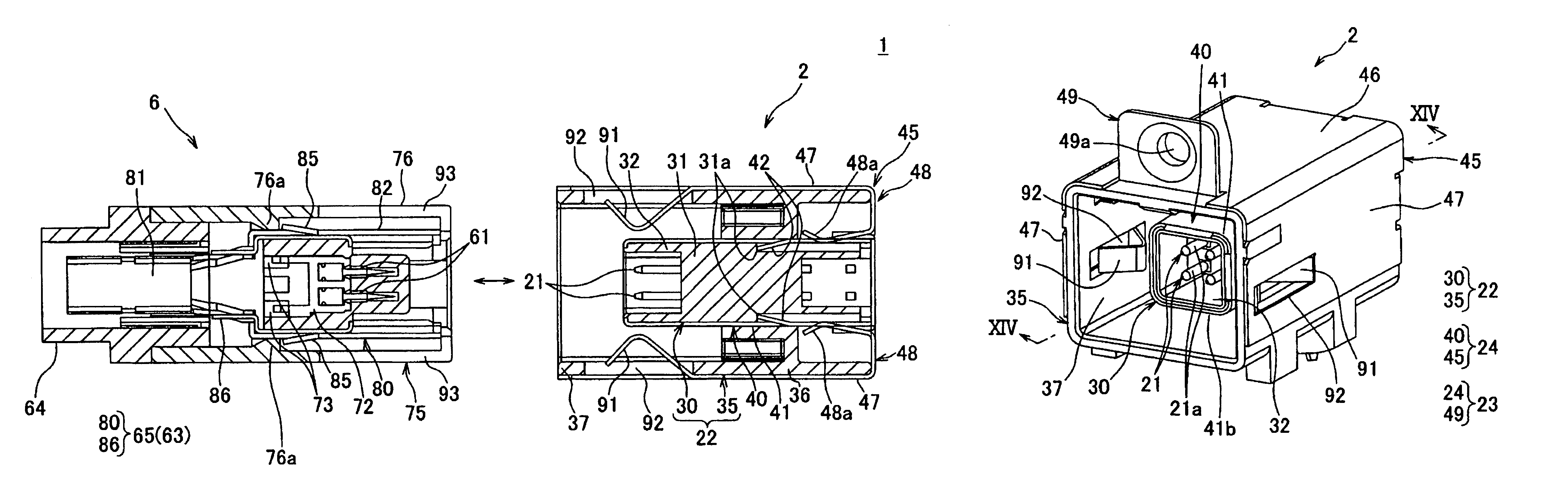
[0100]In this embodiment, unlike the first embodiment, the connection portion 83 is not provided in the lower shield shell 80 of the other connector 6, but a second connection portion 91 is provided in the outer shield shell 45 of one connector 2.

[0101]As shown in FIGS. 9 and 13, the second connection portion 91 is provided in each side plate portion 47 of the pair of side plate portions 47 of the outer shield shell 45. The second connection portion 91 is formed by cutting a part of the side plate portion 47 so as to be bent toward the inside of the outer shield shell 45. The second connection portion 91 is formed in a band plate shape in a direction in which the connectors 2 and 6 are fitted to each other, where one end on the side of the other connector 6 is a free end and the other end away from the other connector 6 is connected to the side plate portion 47. The second connection portion 91 is bent at the center in a longitudinal direction, and a gap between the pair of second c...


PUM


Abstract

A shield connector structure 1 includes a pair of connectors 2 and 6 that is capable of being fitted to each other and a conductive connector attachment portion 11. One connector 2 includes a terminal metal part 21, an insulating connector housing 22, and a conductive shield shell 23. The other connector 6 includes a terminal metal part 61, an insulating connector housing 62, and a conductive shield shell 63. The shield shell 23 is provided with a connection portion 49, and the shield shell 63 is provided with a connection portion 83. When the connectors 2 and 6 are fitted to each other so that the shield shells 23 and 63 are shield-connected to each other, each of the connection portions 49 and 83 is connected to the connector attachment portion 11 and the shield shells 23 and 63 are grounded.

Description

BACKGROUND OF THE INVENTION[0001]1. Field of the Invention[0002]The present invention relates to a shield connector structure which includes a conductive connector attachment portion and a pair of connectors each having a conductive shield shell for covering a connector housing used to accommodate a terminal metal part, and which allows the shield shell to contact with the connector attachment portion so that noise or the like is grounded.[0003]2. Description of the Related Art[0004]Various electronic devices are mounted to an automobile that is a moving vehicle. For this reason, the automobile is provided with a wire harness in order to supply a signal or a power to the above-described electronic devices. Such a wire harness includes plural electric wires and connectors attached to the electric wires.[0005]In the above-described automobile, for example, an electric automobile, a hybrid automobile, or a fuel-cell automobile, a driving motor may be configured as a three-phase AC moto...

Claims


Application Information

Patent Timeline
Patent Type & Authority Patents(United States)
IPC IPC(8): H01R13/648H01R13/658
CPCH01R13/65802Y10S439/939H01R2201/26H01R12/716H01R12/724H01R13/6582H01R13/658
Inventor KAMEYAMA, ISAONOJIMA, MOTOO
Owner YAZAKI CORP
Why Eureka
Try Eureka