Method and apparatus for positioning a catheter relative to an anatomical junction

a catheter and junction technology, applied in the field of method and apparatus for positioning a catheter relative to a junction, can solve the problems of inability to close the valve, incompetent valves, and additional valvular failures

Inactive Publication Date: 2010-09-07
TYCO HEALTHCARE GRP LP
View PDF71 Cites 96 Cited by
  • Summary
  • Abstract
  • Description
  • Claims
  • Application Information

AI Technical Summary

Benefits of technology

[0014]In another aspect of the invention, the feedback from the catheter is based on a characteristic measured at the working end of the catheter to determine the flow rate in the vein. The flow rate should increase going from the saphenous vein to the femoral vein at the sapheno-femoral junction. Where the flow rate is determined w

Problems solved by technology

When an incompetent valve 28 is in the flow path, the valve is unable to close because the cusps do not form a proper seal and retrograde flow of the blood cannot be stopped.
When a venous valve fails, increased strain and pressure occur within the lower venous sections and overlying tissues, sometimes leading to additional valvular failure.
Incompetent valves may result from the stretching of dilated veins.
As the valves fail, increased pressure is imposed on the lower veins and the lower valves of the vein, which in turn exacerbates the failure of these lower valves.
The varicose vein condition includes dilation and tortuosity of the superficial veins of the lower limbs, resulting in unsightly discoloration, pain, swelling, and possibly ulceration.
This can also worsen deep venous reflux and perforator reflux.
As the valves in the veins fail, the hydrostatic pressure increases on the next venous valves down, causing those veins to dilate.
As this continues, more venous valves will eventual

Method used


Image

  • Method and apparatus for positioning a catheter relative to an anatomical junction
  • Method and apparatus for positioning a catheter relative to an anatomical junction
  • Method and apparatus for positioning a catheter relative to an anatomical junction

Examples


Embodiment Construction

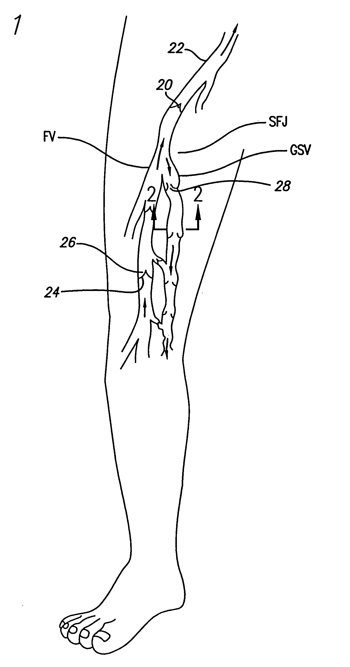
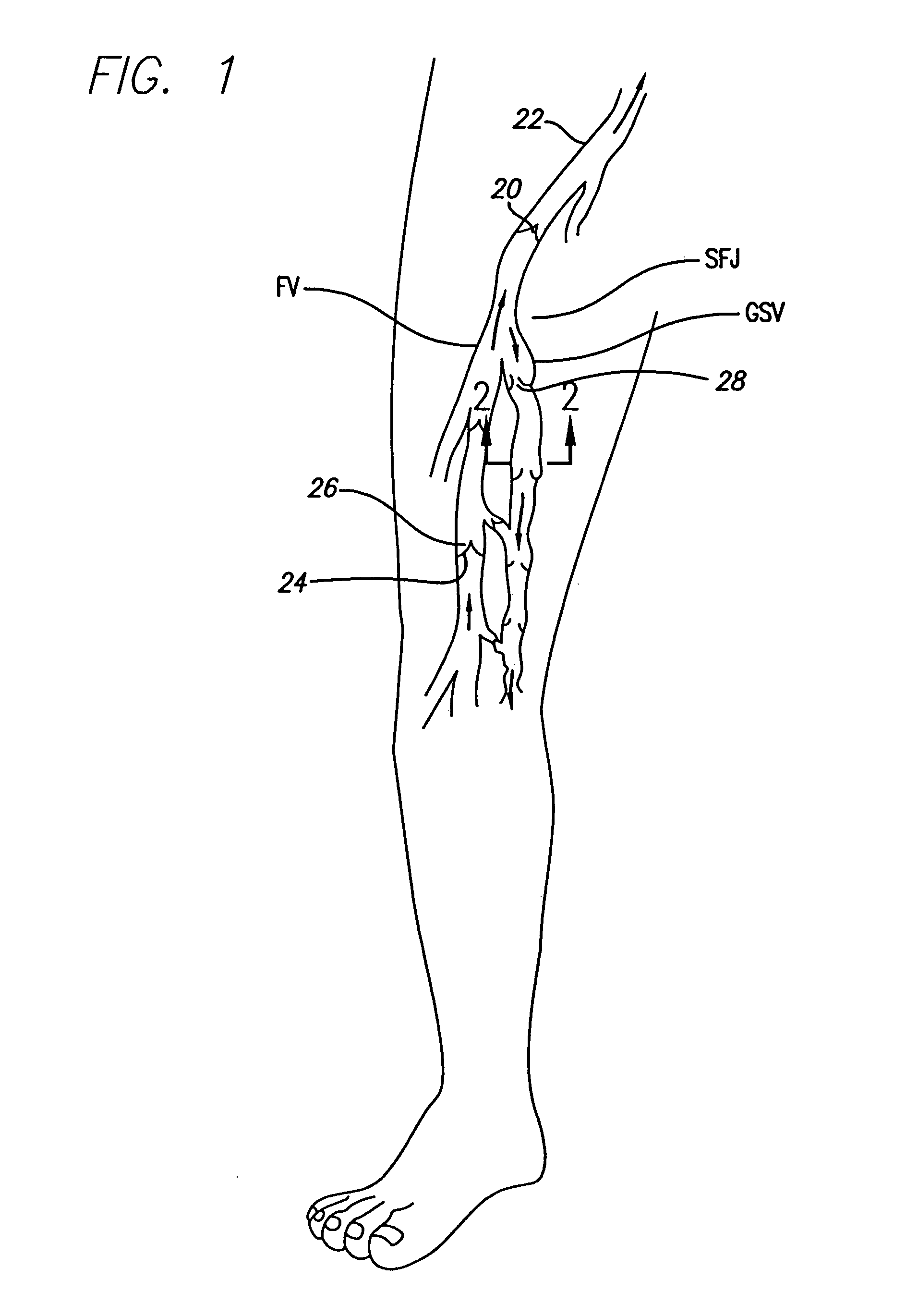
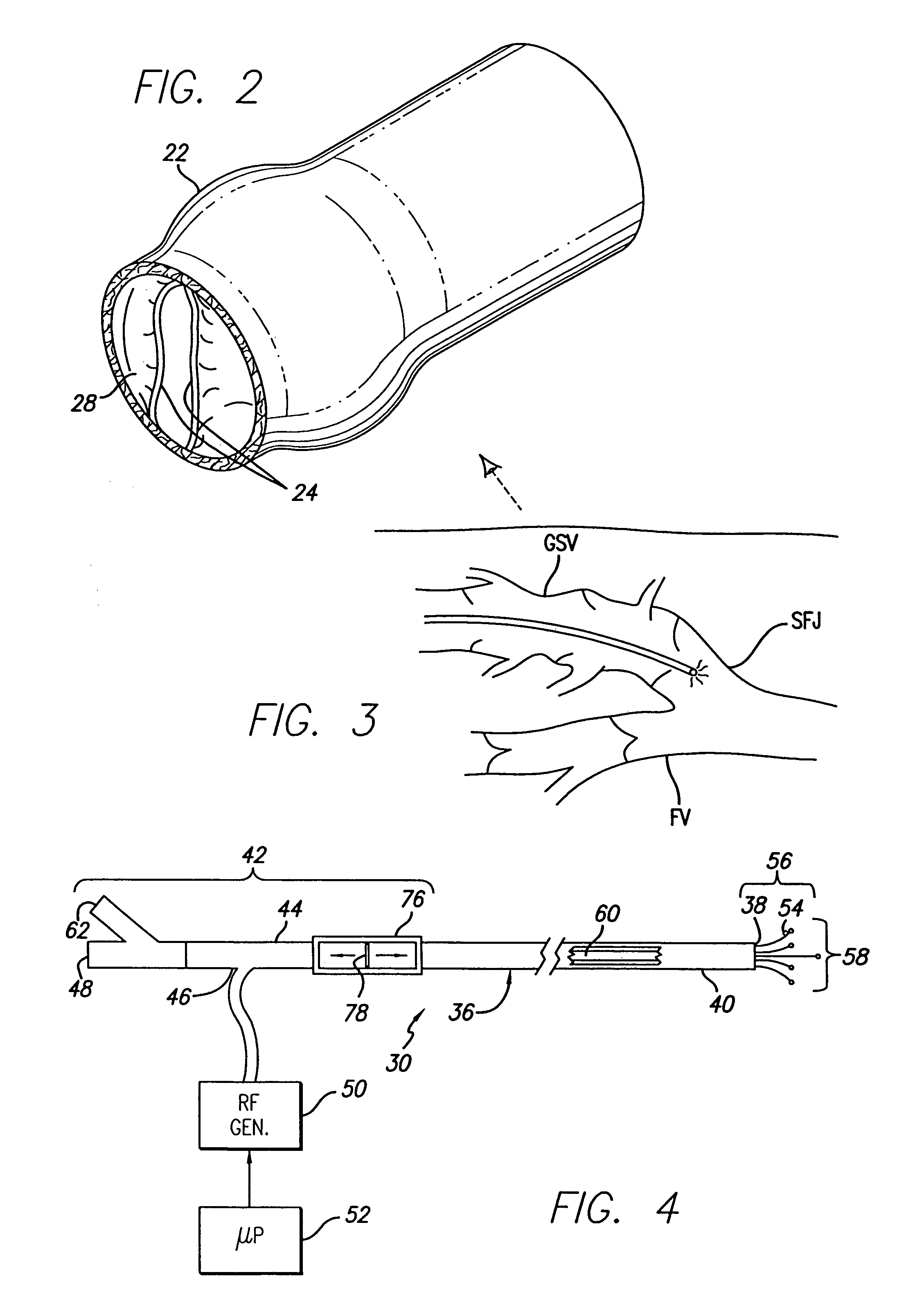
[0031]As shown in the exemplary drawings, the invention is directed toward the positioning of a catheter to a treatment site for the intravenous treatment of veins. As used herein, like reference numerals will designate similar elements in the various embodiments of the present invention to be discussed. In addition, unless otherwise noted, the term “working end” will refer to the direction toward the treatment site in the patient, and the term “connecting end” will refer to the direction away from the treatment site in the patient. Although the use of RF energy is discussed, it is to be understood that other forms of energy such as microwaves, ultrasound, direct current, circulating heated fluid, radiant light, and lasers can be used, and that the thermal energy generated from a resistive coil or curie point element may be used as well. The invention will be described in relation to the treatment of the venous system of the lower limbs, such as the saphenous vein in the leg. It is ...


PUM


Abstract

An electrode catheter is introduced into a vein or other hollow anatomical structure, and is positioned at a treatment site within the structure. The end of the catheter is positioned near a junction formed in the structure. This junction can be the sapheno-femoral junction. The position of the catheter near the junction is determined based on a signal from a device associated with the catheter within the structure. A fiber optic filament which emits light is used with the catheter or a guide wire over which the catheter is advanced. The light is visible externally from the patient. The light dims and may no longer externally visible at the sapheno-femoral junction where the catheter moves past the deep fascia and toward the deep venous system. The position of the catheter can be determined based on this external observation. The position of the catheter can also be determined based on measured parameters such as temperature or flow rate within the structure, and the measured changes in one or more of these parameters as the catheter nears the junction. The hollow anatomical structure can be compressed for this procedure. The position of the catheter can also be determined mechanically by including a hook-shaped tip on the catheter or guide wire which would physically engage the junction.

Description

BACKGROUND[0001]The invention relates generally to a method and apparatus for positioning a catheter relative to a junction in a hollow anatomical structure, such as a vein, including but not limited to, superficial and perforator veins, hemorrhoids, and esophageal varices. The catheter can include an electrode device having multiple leads for applying energy to the anatomical structure to cause it to durably assume a ligated form.[0002]The human venous system of the lower limbs consists essentially of the superficial venous system and the deep venous system with perforating veins connecting the two systems. The superficial system includes the long or great saphenous vein (GSV) and the short saphenous vein. The deep venous system includes the anterior and posterior tibial veins which unite to form the popliteal vein, which in turn becomes the femoral vein (FV) when joined by the short saphenous vein. As illustrated in FIG. 1, The great saphenous vein (GSV) travels through the deep f...

Claims


Application Information

Patent Timeline
IPC IPC(8): A61B18/18A61B18/14A61M25/01
CPCA61B18/1492A61B19/5244A61B2017/00867A61B2017/22038A61B2018/00273A61B2018/00404A61B2018/00797A61B2018/00815A61B2018/00821A61B2018/00875A61B2018/1253A61B2018/1467A61B2018/1475A61B2019/5251A61M25/01C08L2201/12A61B34/20A61B2034/2051
Inventor ZIKORUS, ARTHUR W.DEPALMA, RALPH G.JONES, CHRISTOPHER S.FARLEY, BRIAN E.CHANDLER, JAMES G.
Owner TYCO HEALTHCARE GRP LP
Why Eureka
Try Eureka