Exhaust gas purification device of internal combustion engine

a technology of exhaust gas purification device and internal combustion engine, which is applied in the direction of machines/engines, electrical control, separation processes, etc., can solve the problems of affecting the safety and reliability and affecting the operation of the whole system. the effect of reducing the calculation of the amount of particulate matter deposition or regeneration control, reducing the deterioration of controllability or melt damage of the filter

Active Publication Date: 2010-09-21
DENSO CORP
View PDF3 Cites 3 Cited by
  • Summary
  • Abstract
  • Description
  • Claims
  • Application Information

AI Technical Summary

Benefits of technology

[0011]It is an object of the present invention to provide an exhaust gas purification device capable of sensing erroneous mounting of multiple exhaust temperature sensors, which are provided in an exhaust flow passage for sensing temperature of an exhaust gas after treatment device, and of safely performing exhaust temperature control based on outputs of the exhaust temperature sensors with high controllability.
[0013]If the operation state changes, the exhaust temperature on the inlet side of the exhaust gas after treatment device such as a particulate filter changes first. The outlet side exhaust temperature changes in retard of the inlet side temperature because of a heat capacity of the filter. Therefore, the erroneous mounting can be detected by comprehending the changes of the exhaust temperature at the time when the operation state changes rapidly and by comparing the deviation value of the change speeds of the exhaust temperature sensed by the exhaust temperature sensors with a normal value. Thus, an influence on various types of control based on the sensed temperature such as calculation of a particulate matter deposition amount or regeneration control can be reduced. Moreover, deterioration of controllability or melt damage of the filter due to erroneous sensing can be inhibited. As a result, safety and reliability of a whole system can be improved.

Problems solved by technology

The controller has an erroneous mounting detector that determines that the exhaust temperature sensors are mounted erroneously if a speed change deviation value deviates from a predetermined normal range in an operation state in which the temperature of the exhaust gas flowing through the exhaust gas after treatment device changes rapidly.
Moreover, deterioration of controllability or melt damage of the filter due to erroneous sensing can be inhibited.

Method used


Image

  • Exhaust gas purification device of internal combustion engine
  • Exhaust gas purification device of internal combustion engine
  • Exhaust gas purification device of internal combustion engine

Examples


Embodiment Construction

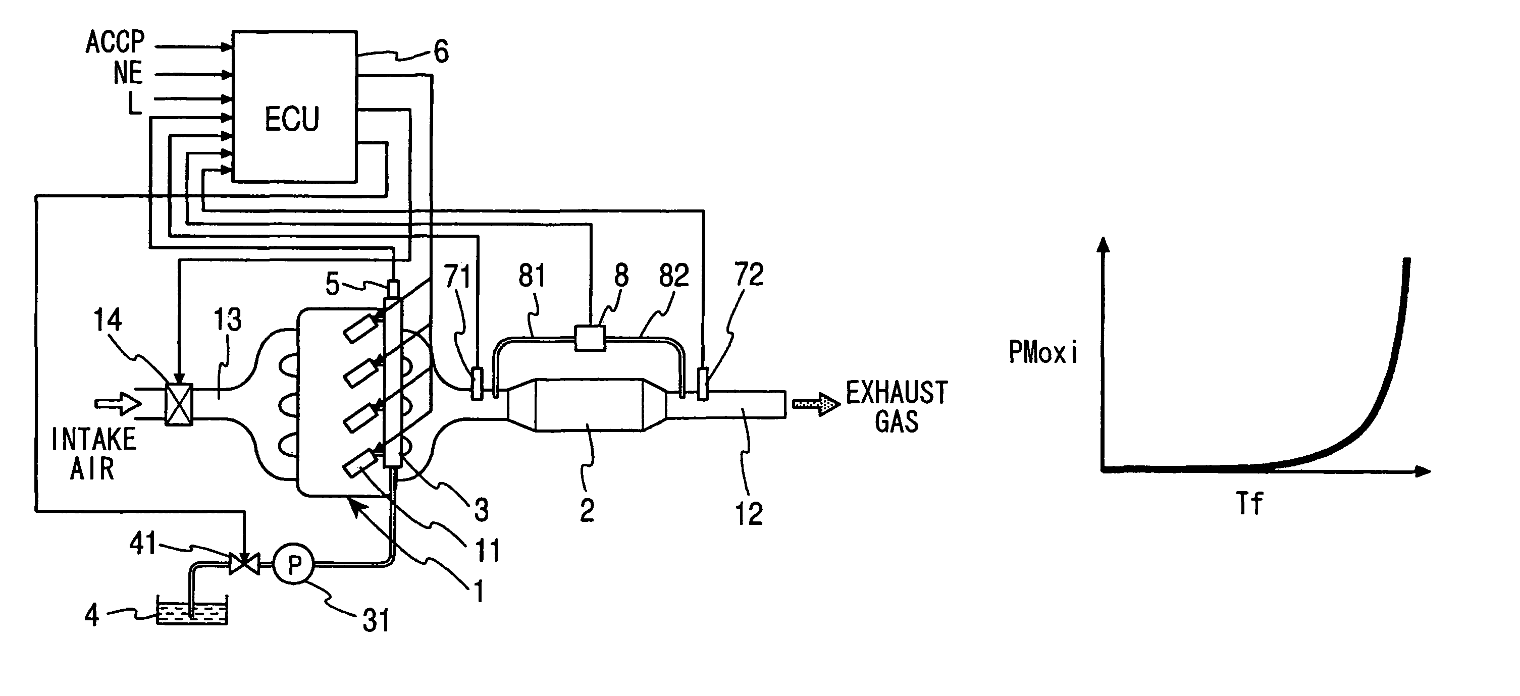
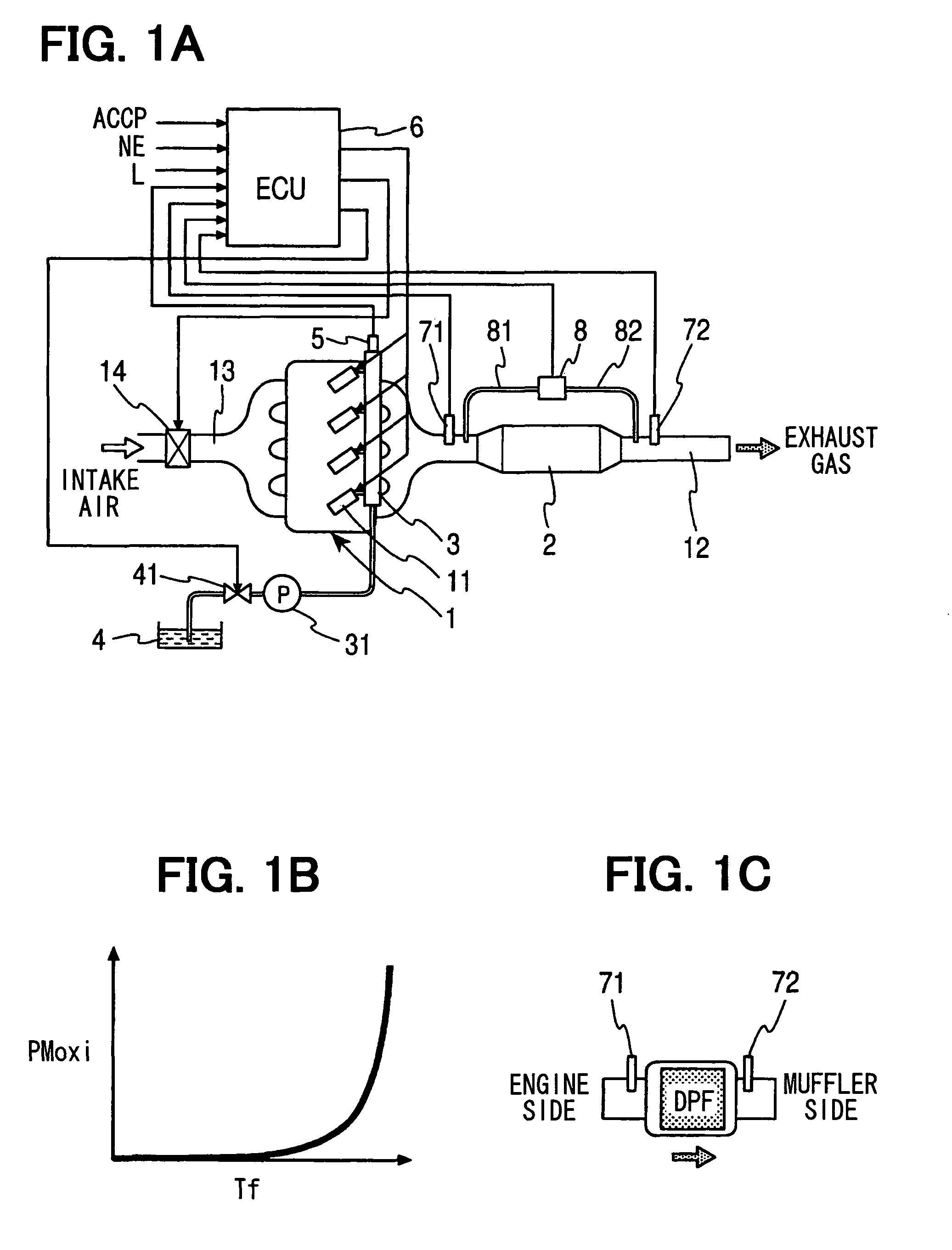
[0033]Referring to FIG. 1A, an exhaust gas purification device of an internal combustion engine according to an example embodiment of the present invention is illustrated. As an example, the exhaust gas purification device of the present embodiment is applied to a four-cylinder diesel engine 1. Injectors 11 are provided in cylinders respectively. A diesel particulate filter (DPF) 2 as an exhaust gas after treatment device is provided in an exhaust passage 12 extending from an exhaust manifold. Intake air is introduced from an intake passage 13 into combustion chambers of the respective cylinders through an intake manifold. Fuel is pressure-fed from a fuel tank 4 to a common rail 3 through a metering valve 41 and a pump 31. The common rail 3 supplies the fuel to the injectors 11. An ECU 6 performs control to conform the pressure in the common rail 3 sensed by a pressure sensor 5 to a predetermined pressure.

[0034]Exhaust gas generated through the combustion contains particulate matter...


PUM

PropertyMeasurementUnit
temperature Tfraaaaaaaaaa
exhaust temperatureaaaaaaaaaa
temperatureaaaaaaaaaa

Abstract

An ECU performs exhaust temperature control based on output values of multiple exhaust temperature sensors provided upstream and downstream of a particulate filter provided in an exhaust passage of an engine. The ECU calculates a change speed deviation value by subtracting change speed of outlet side exhaust temperature, which is sensed by one of the exhaust temperature sensors, from change speed of inlet side exhaust temperature, which is sensed by the other one of the exhaust temperature sensors, in an operation state in which temperature of exhaust gas flowing through the particulate filter changes rapidly. The ECU determines that the exhaust temperature sensors are mounted erroneously if the change speed deviation value deviates from a predetermined normal range.

Description

CROSS REFERENCE TO RELATED APPLICATION[0001]This application is based on and incorporates herein by reference Japanese Patent Application No. 2005-373012 filed on Dec. 26, 2005.BACKGROUND OF THE INVENTION[0002]1. Field of the Invention[0003]The present invention relates to an exhaust gas purification device having an exhaust gas after treatment device in an exhaust passage of an internal combustion engine. Specifically, the present invention relates to detection of erroneous mounting of exhaust temperature sensors provided in the exhaust passage upstream and downstream of a particulate filter.[0004]2. Description of Related Art[0005]A diesel particulate filter (DPF) is attracting attention as an exhaust gas after treatment device of a diesel engine. The DPF is formed with multiple flow passages defined by porous ceramic walls inside. The DPF collects particulate matters contained in exhaust gas when the exhaust gas flowing into the flow passages passes through the porous ceramic wal...

Claims


Application Information

Patent Timeline
Patent Type & Authority Patents(United States)
IPC IPC(8): F01N3/00F01N3/10B01D46/42F01N3/02F01N3/021F01N3/023F01N3/035F01N3/24F02D45/00
CPCF01N11/00Y02T10/47Y02T10/40
Inventor KUSATSUGU, HIDEYUKI
Owner DENSO CORP
Why Eureka
Try Eureka