Vehicle seat air-conditioner and vehicle temperature controller

a technology for vehicle seats and air conditioners, which is applied in the direction of machines, instruments, chairs, etc., can solve the problems of increasing the thickness of the cushion body, hindering the application of thin seats, and affecting the warmth or coolness sensation

Inactive Publication Date: 2010-11-09
HONDA MOTOR CO LTD
View PDF17 Cites 72 Cited by
  • Summary
  • Abstract
  • Description
  • Claims
  • Application Information

AI Technical Summary

Benefits of technology

[0011]In view of these circumstances, it is therefore a first object of the present invention to provide a vehicle seat air-conditioner that can achieve a further improvement air condition performance.
[0012]In addition, it is a second object of the present invention to provide a vehicle seat air-conditioner that can also be applied to thin seats without sacrificing sitting comfort.
[0013]Furthermore, it is a third object of the present invention to provide a vehicle temperature controller that can simultaneously achieve both sitting comfort and a reduction in energy consumption.
[0021]The integrated control device may correct upward a target control temperature of the cabin air-conditioner when the seat is in a cooled state by the seat temperature adjustment device.
[0022]The integrated control device may correct downward a target control temperature of the cabin air-conditioner when the seat is in a heated state by the seat temperature adjustment device.

Problems solved by technology

However, among such conventional vehicle seat air-conditioners, in the former, since the seat covering layer in contact with the occupant is heated or cooled through the heat-exchange chamber on the underside thereof, depending on the sitting posture and body shape of the occupant, contact with the seat covering layer may be inadequate, thereby hindering sensation of warmth or coolness.
Moreover, since the latter has the configuration in which a blower is disposed at the bottom of the cushion body of a seat cushion and a plurality of flow passages connecting the blower and the blow-out holes in the seat covering material are formed in the cushion body, in order to secure sufficient flow passage area of the conditioned gas while maintaining sitting comfort, it is necessary to increase the thickness of the cushion body, thereby hindering the application to thin seats.

Method used


Image

  • Vehicle seat air-conditioner and vehicle temperature controller
  • Vehicle seat air-conditioner and vehicle temperature controller
  • Vehicle seat air-conditioner and vehicle temperature controller

Examples


first embodiment

[0039]Below, an example of the vehicle seat air-conditioner according to the present invention will be explained with reference to FIGS. 1A to 5 as the present invention.

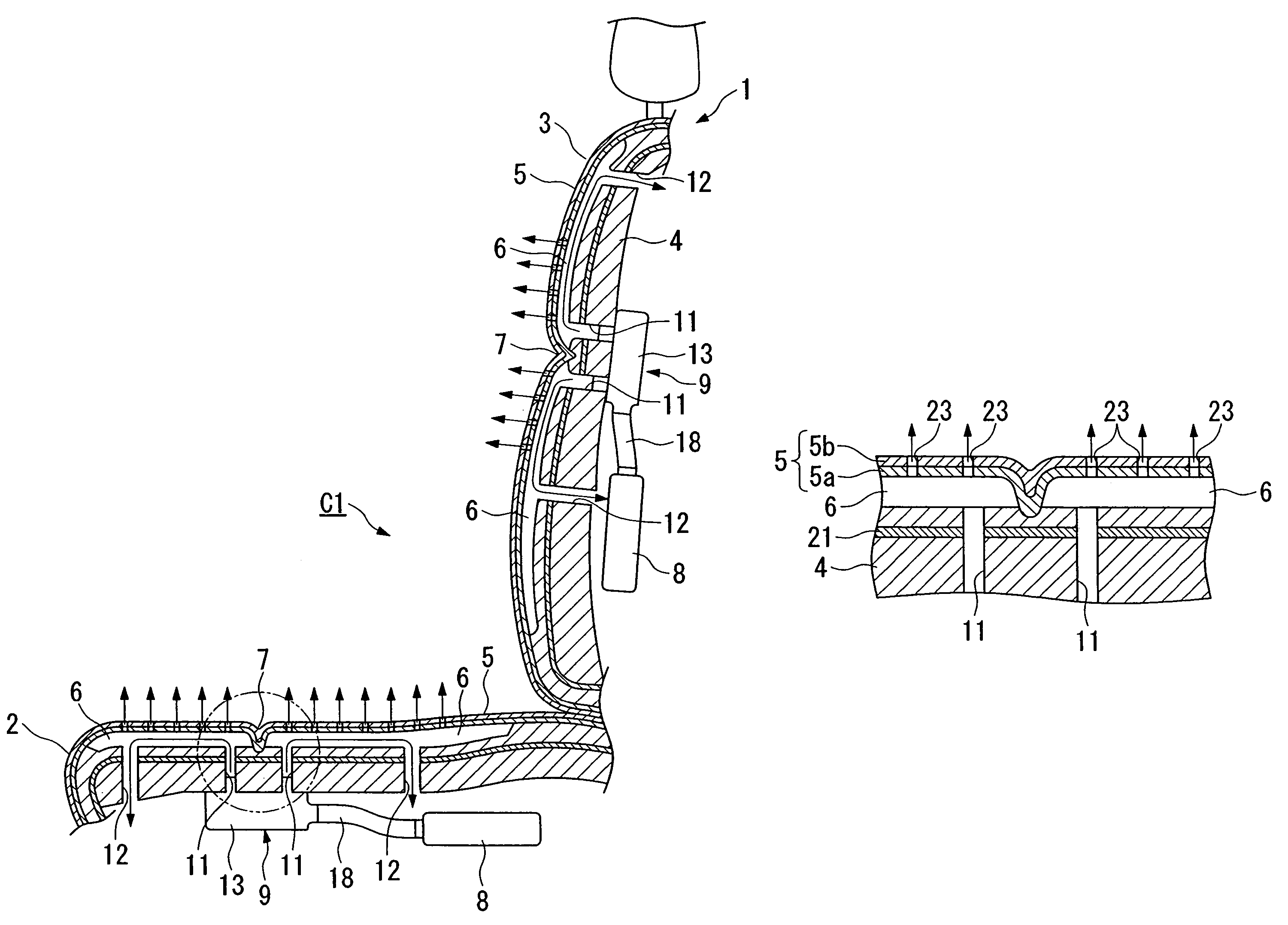
[0040]As shown in FIGS. 1A and 1B, this vehicle seat air-conditioner C1 has a constitution including at least a seat 1 such as a driver's seat or a passenger seat, a seat covering layer 5 described hereinbelow, a blower 8, and a heat-exchange chamber (flow passage) 6.

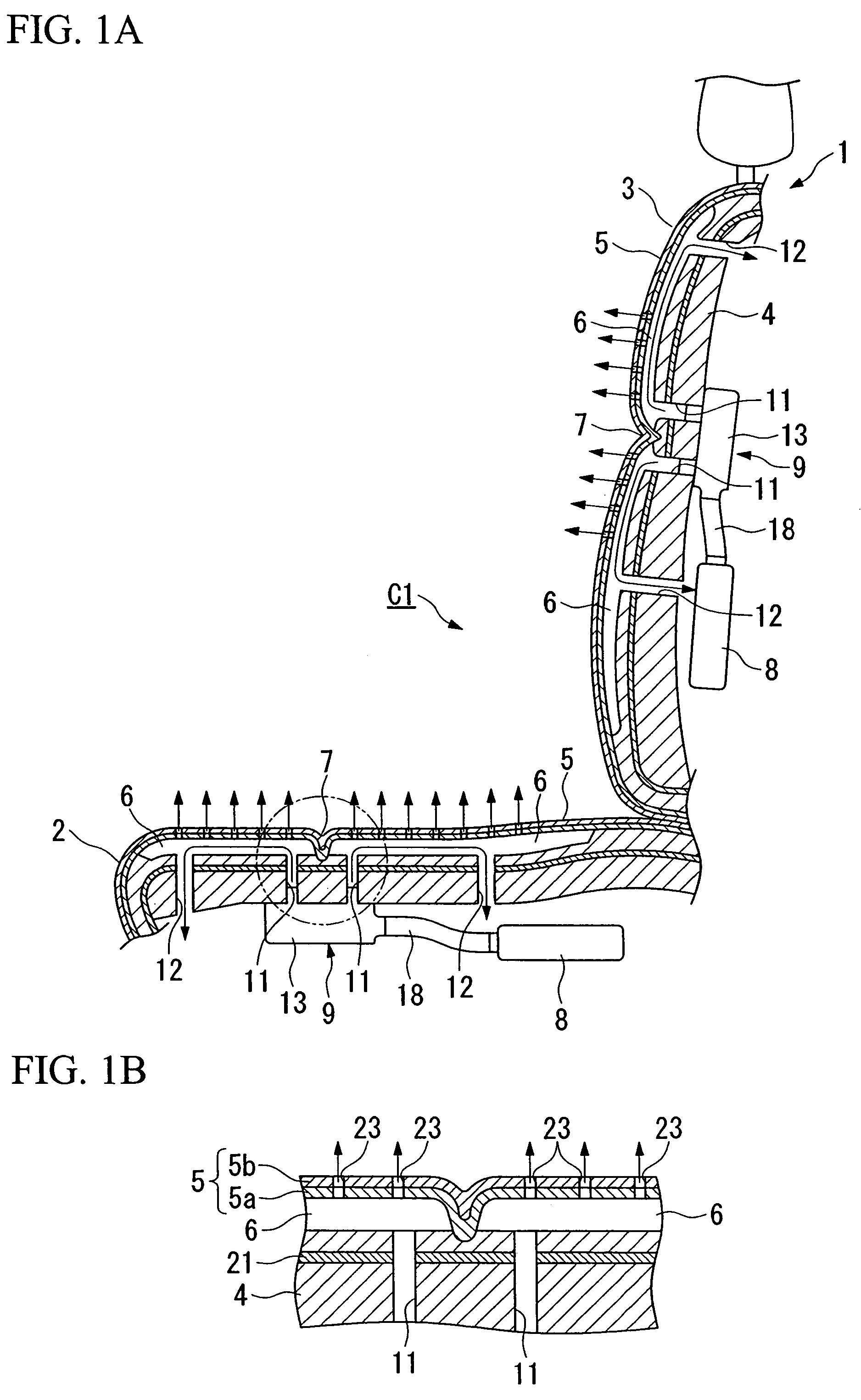
[0041]As shown in FIG. 2, identical constituent devices are arranged in a seat cushion 2 and a seat back 3 that constitute the seat 1. Hereinbelow, the constitution of the seat cushion 2 will be explained in detail, with identical portions of the seat back 3 side having the same reference numerals and redundant descriptions being omitted. Moreover, hereinbelow, air (gas) that is heated or cooled for cooling or heating is referred to “conditioned gas”.

[0042]A cushion body 4 of the seat cushion 2 is covered with the seat covering layer 5 as shown in FIGS....

second embodiment

[0055]As the present invention, other examples of the vehicle seat air-conditioner according to the present invention will be explained with reference to FIGS. 7 to 11.

[0056]As shown in FIG. 7, a vehicle seat air-conditioner C2 has a constitution equipped with at least a seat 101, such as a driver's seat or a passenger seat, a seat covering material (seat covering layer) 106 described hereinbelow, a blower 17, and flow passages that circulate conditioned gas. In addition, in FIG. 8, 102 is a seat cushion, 103 a seat back and 104 a headrest.

[0057]The seat cushion 102 has a basic structure in which a cushion body 105 consisting of a pad material is covered with the seat covering material 106, with side support portions 108, having a cross-section bulging in a mountain shape, provided on both sides of a sitting portion 107 on which an occupant sits. A sheet-shaped rigidity support material 109 (for example, material called a “Space fabric” (registered trademark)) having permeability is...

third embodiment

[0068]Next, as the present invention, an example of the vehicle temperature controller according to the present invention is explained with reference to FIGS. 13 to 15.

[0069]FIG. 13 shows a general structure of the vehicle temperature controller according to the present invention. A vehicle temperature controller C10 includes a cabin air-conditioner 201 that adjusts the in-cabin air conditioning temperature; a seat temperature adjustment device 202 that adjusts the temperature of a seat; and an electronic control unit (integrated control device: hereafter referred to as “ECU”) 203 that carries out integrated control of the aforementioned devices.

[0070]Provided in the cabin air-conditioner 201 are a fan duct 204, an outside air inlet 205 that takes in the air outside a vehicle (outside air) to the upstream side of the fan duct 204, and an inside air inlet 206 that sucks in the air in the cabin (inside air). In addition, near the outside air inlet 205 and the inside air inlet 206 is p...


PUM


Abstract

A vehicle seat air-conditioner includes a seat on which an occupant sits, a seat temperature adjustment device that adjusts the temperature of a conditioned gas, a blower that supplies the conditioned gas to the seat, a seat covering layer provided on a surface of the seat and facing the seated occupant, and a flow channel provided on an underside of the seat covering layer that pass the conditioned gas that is introduced by the blower. The vehicle seat air-conditioner is adapted to convey heat of the conditioned gas to an occupant side of the seat covering layer by directly blowing out a portion of the introduced conditioned gas to the occupant side of the seat covering layer, and to perform heat exchange with the occupant side of the seat covering layer by circulating a portion of a remainder of the conditioned gas through the flow channel.

Description

BACKGROUND OF THE INVENTION[0001]1. Field of the Invention[0002]This invention relates to a vehicle seat air-conditioner that performs air conditioning through a seat on which an occupant sits, and a vehicle temperature controller that carries out integrated control of air conditioning inside the vehicle and temperature adjustment of the seat portion.[0003]The present application claims priority on Japanese Patent Application No. 2004-255524, filed Sep. 2, 2004, Japanese Patent Application No. 2004-266642, filed Sep. 14, 2004, and Japanese Patent Application No. 2004-268139, filed Sep. 15, 2004, the contents of which are incorporated herein by reference.[0004]2. Description of Related Art[0005]A vehicle seat air-conditioner has been devised to heat or cool an occupant by providing a heat-exchange chamber on the underside of the seat covering layer that contacts the seated occupant, and controlling the conditioned air (conditioned gas) introduced into the heat-exchange chamber (see, ...

Claims


Application Information

Patent Timeline
Patent Type & Authority Patents(United States)
IPC IPC(8): B60H1/00A47C7/72A47C31/00
CPCB60H1/00285B60N2/5825B60N2/5635B60N2/5628B60H2001/003
Inventor ESAKI, HIDENORI
Owner HONDA MOTOR CO LTD
Why Eureka
Try Eureka