Operation method of heat pump-type vehicle air conditioning system

a technology of vehicular air conditioning and operation method, which is applied in the direction of heat pumps, domestic cooling devices, lighting and heating devices, etc., can solve the problems of uneconomical vehicular air conditioning devices and lowered air-conditioning performance, and achieve the effect of increasing the work efficiency of the compressor, increasing the pressure of the refrigerant, and quick heating the cabin

Inactive Publication Date: 2013-01-17
HONDA MOTOR CO LTD
View PDF0 Cites 10 Cited by
  • Summary
  • Abstract
  • Description
  • Claims
  • Application Information

AI Technical Summary

Benefits of technology

[0007]The present invention has been made in an effort to solve the aforementioned problems. An object of the present invention is to provide a heat-pump type vehicular air conditioning system, which is capable of selecting either a heating capability priority or an operation efficiency priority depending on inside and outside temperatures of a passenger compartment, for enabling good air conditioning capability and improving economic efficiency.
[0010]According to the present invention, when a pressure loss is imparted to the refrigerant by the pressure loss device, the pressure of the refrigerant is increased, and in addition, the amount of work performed by the compressor is increased. Therefore, the temperature of the air-conditioning air, which is heat-exchanged by the heater, is increased when the air-conditioning air is discharged into the cabin, thereby quickly heating the cabin (cold-climate operating mode).
[0011]When the pressure loss imparted to the refrigerant is reduced, the pressure of the refrigerant is lowered, and in addition, the amount of work performed by the compressor is lowered. Therefore, a heating COP (a measure of heating ability per heating electric power consumption) is increased for allowing the air conditioning system to operate economically in a heating mode (normal operating mode).
[0012]Therefore, the vehicular air conditioning system is capable of selecting either a heating capability priority or an operation efficiency priority, depending on the temperatures inside and outside of the cabin, for thereby enabling good air conditioning capability and improving economic efficiency.

Problems solved by technology

Therefore, the number of components dedicated to the heating mode is increased, thereby making the vehicular air conditioning apparatus uneconomical.
Consequently, due to the refrigerant shortage, air-conditioning performance is lowered.

Method used


Image

  • Operation method of heat pump-type vehicle air conditioning system
  • Operation method of heat pump-type vehicle air conditioning system
  • Operation method of heat pump-type vehicle air conditioning system

Examples


first embodiment

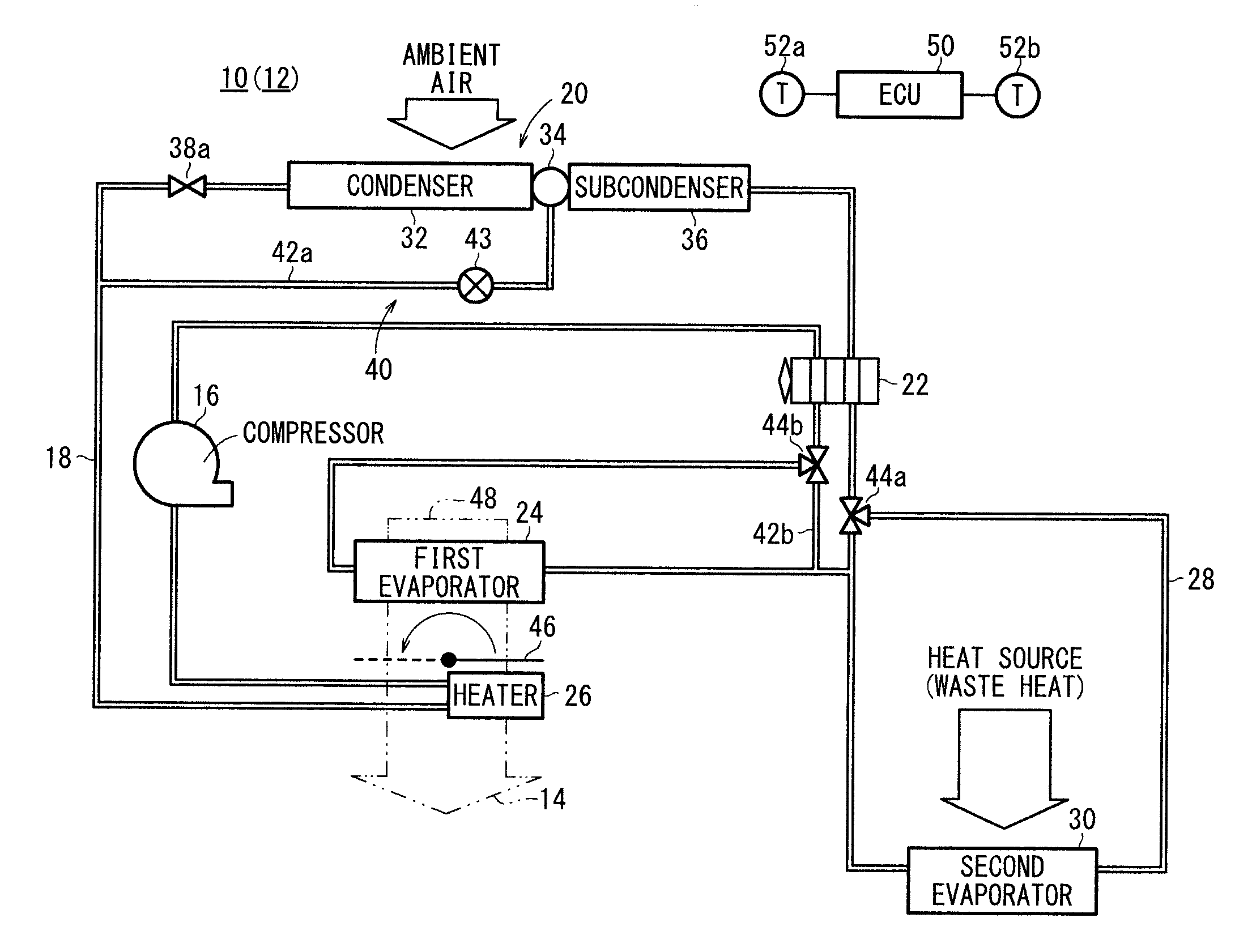
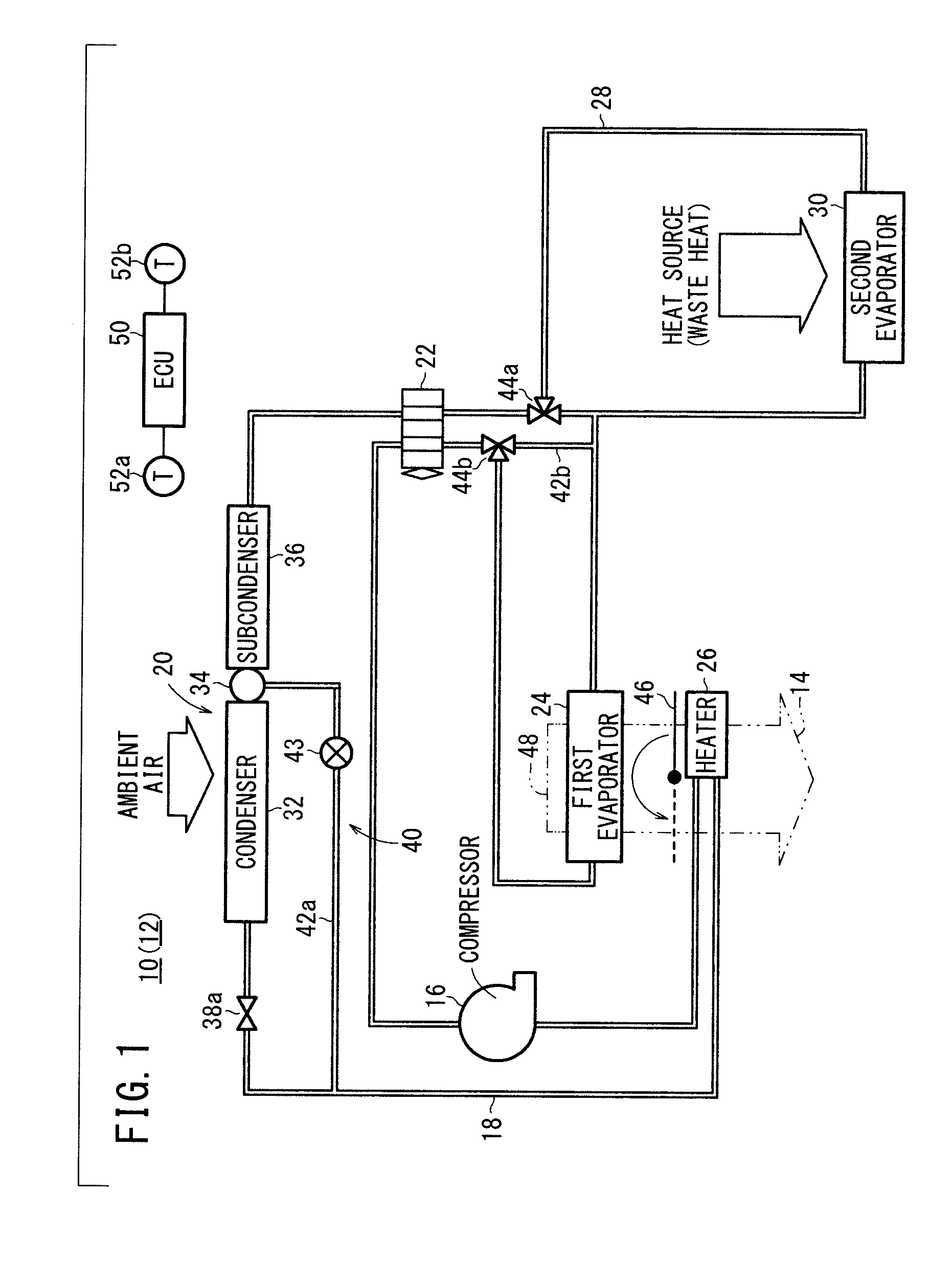
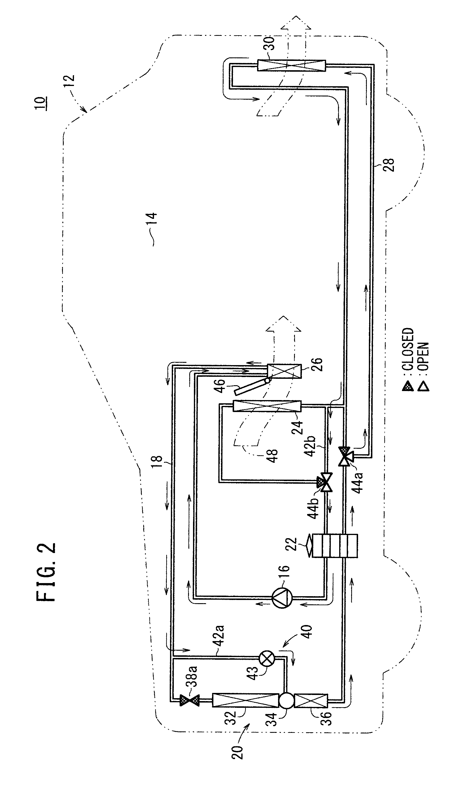
[0025]As shown in FIGS. 1 and 2, a heat pump-type vehicular air conditioning system 10 to which an operating method according to the present invention is applied is incorporated in an automobile (vehicle) 12 for air-conditioning a passenger cabin (vehicle compartment) 14 of the automobile 12.

[0026]The air conditioning system 10 includes a heat pump circulation path 18 for circulating a refrigerant with a compressor 16. The heat pump circulation path 18 includes therein a condenser unit (subcooling condenser) 20 for performing heat exchange between the refrigerant and ambient air, an expansion valve 22 for depressurizing the refrigerant delivered from the condenser unit 20, a first evaporator 24 for performing heat exchange between the refrigerant, which has passed through the expansion valve 22, and air-conditioning air, and a heater 26 for performing heat exchange between the refrigerant, which has been delivered from the compressor 16, and the air-conditioning air, which has passe...

second embodiment

[0054]FIG. 9 is a schematic block diagram of a heatpump type vehicular air conditioning system 70 to which an operating method according to the present invention is applied.

[0055]Parts of the air conditioning system 70 according to the second embodiment, which are identical to those of the air conditioning system 10 according to the first embodiment, are denoted by identical reference characters, and such features will not be described in detail below.

[0056]The air conditioning system 70 includes a bypass unit 72, which connects the heater 26 and the gas-liquid separation refrigerant storage unit 34 to each other in bypassing relation to the condenser 32 in the heating mode. The bypass unit 72 includes a first bypass passage 42a and a third bypass passage 42c, together with a capillary 74, which is connected to the first bypass passage 42a and functions as a pressure loss device for imparting a pressure loss to the refrigerant. A solenoid-operated valve 38b is connected upstream of ...


PUM


Abstract

The disclosed operation method of a heat pump-type vehicle air conditioning system involves a step for setting a cold operating mode for raising the output air temperature of the air conditioner by means of a heater or a normal operating mode for raising the heating COP; a step for detecting the temperatures inside and outside the vehicle; and a step which, by selecting either the cold operating mode or the normal operating mode on the basis of the detected temperatures inside and outside of the vehicle, is for bypassing a condenser, controlling the opening of an electronic expansion valve contained in a bypass unit connected in series to a gas / liquid separating liquid coolant storage unit downstream of the aforementioned heater, and adjusting the pressure drop applied to the coolant.

Description

TECHNICAL FIELD[0001]The present invention relates to a method of operating a heat-pump type vehicular air conditioning system incorporated in a vehicle for air-conditioning the passenger cabin of the vehicle.BACKGROUND ART[0002]Vehicles, e.g., engine automobiles having an internal combustion engine, hybrid automobiles having an engine and a secondary battery (or a secondary battery and a fuel cell or the like) in combination, electric automobiles, and fuel cell automobiles, incorporate various types of vehicular air conditioning systems therein.[0003]For example, as shown in FIG. 12, the vehicular air conditioning apparatus disclosed in Japanese Laid-Open Patent Publication No. 2009-023564 includes a compressor 1 for drawing in and discharging a refrigerant, a condenser 3 disposed in an air conditioning unit case 2 for heating air by performing heat exchange between air and the refrigerant that is discharged from the compressor 1 in a heating mode, a receiver 4 for receiving refrig...

Claims


Application Information

Patent Timeline
Patent Type & Authority Applications(United States)
IPC IPC(8): B60H1/32B60H1/00
CPCB60H1/00914B60H1/3213B60H1/00921B60H2001/00949F25B6/04F25B30/02F25B40/02F25B2400/0403F25B2400/23F25B2500/31F25B2600/2501F25B2600/2513F25B2700/2104F25B2700/2106B60H1/039F25B41/24
Inventor KIMURA, KENZOYAMAOKA, DAISUKEESAKI, HIDENORIMASUZAWA, KOSUKEKOBAYASHI, SATOSHI
Owner HONDA MOTOR CO LTD
Why Eureka
Try Eureka