Heat exchanger, heat exchanger manufacturing method, and air conditioner

A technology for heat exchangers and manufacturing methods, applied to heat exchange equipment, heating methods, air conditioning systems, etc., capable of solving problems such as processing through holes

Inactive Publication Date: 2005-06-29
DAIKIN IND LTD
View PDF0 Cites 9 Cited by
  • Summary
  • Abstract
  • Description
  • Claims
  • Application Information

AI Technical Summary

Problems solved by technology

However, since the conventional method of manufacturing heat sinks adopts a longitudinal conveying method, it is difficult to process through-holes of different diameters along the longitudinal direction of the heat sink.

Method used


Image

  • Heat exchanger, heat exchanger manufacturing method, and air conditioner
  • Heat exchanger, heat exchanger manufacturing method, and air conditioner
  • Heat exchanger, heat exchanger manufacturing method, and air conditioner

Examples


no. 1 approach

[0035] Hereinafter, a first embodiment of the present invention will be described with reference to the drawings.

[0036] (1) Heat exchanger structure

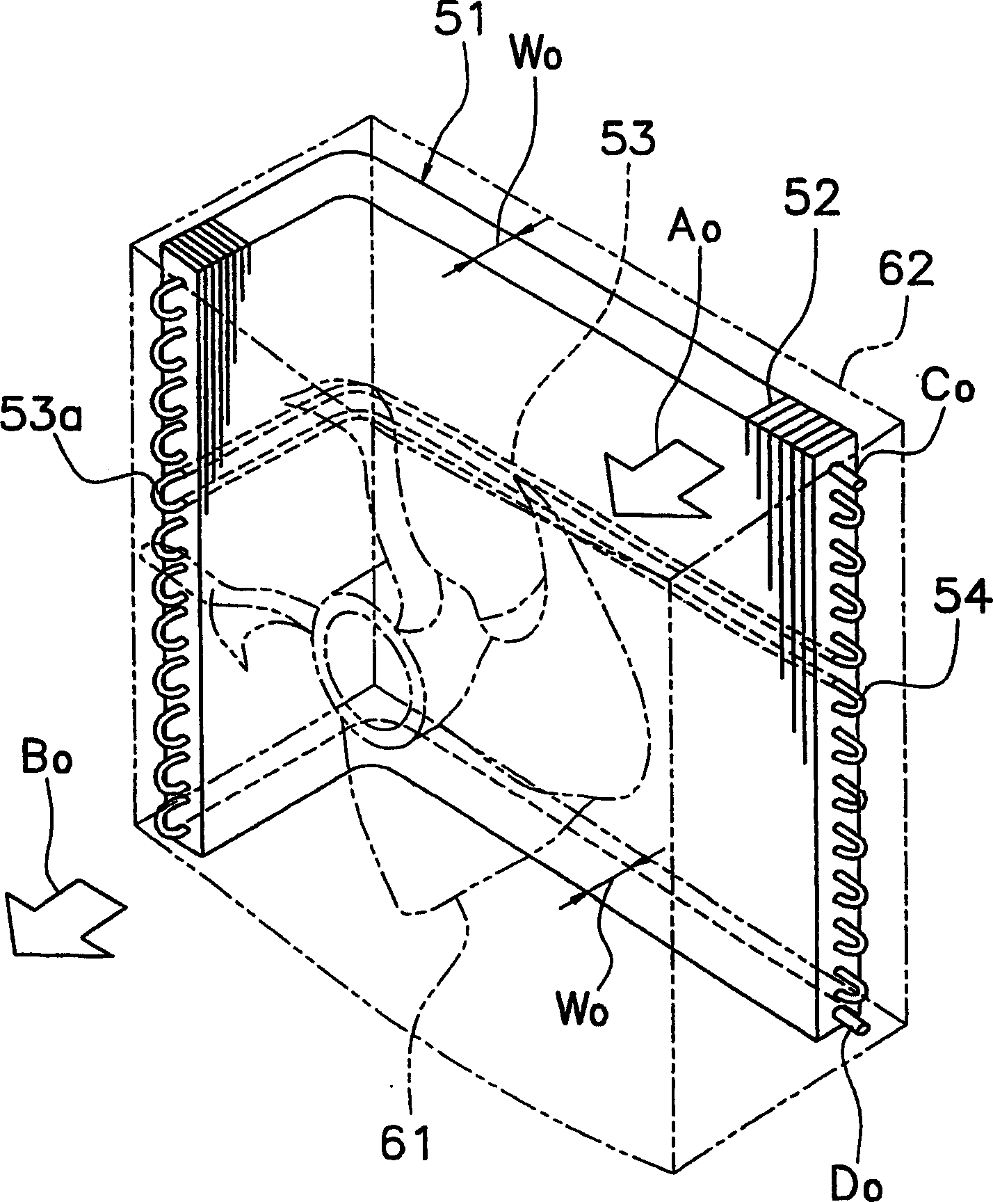
[0037] Figure 4 It is a schematic perspective view showing the outdoor unit of the air conditioner using the heat exchanger 1 according to the first embodiment of the present invention. The heat exchanger 1 is L-shaped, and its purpose is to match the air flow formed by the propeller blower 11 from the back side of the outdoor unit casing 12 to the front side (see arrow A). 1 and B 1 ) for heat exchange to evaporate or condense the refrigerant flowing inside the tube of the heat transfer tube.

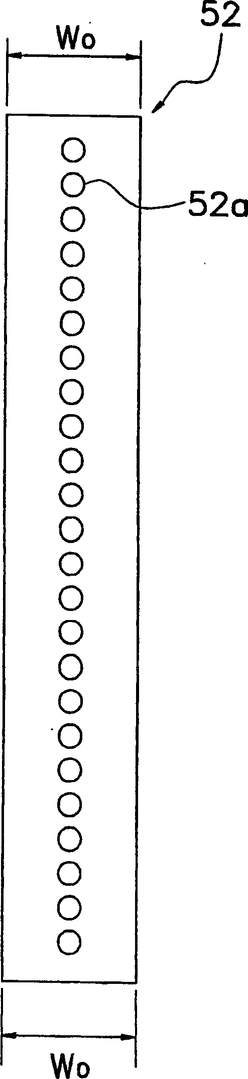
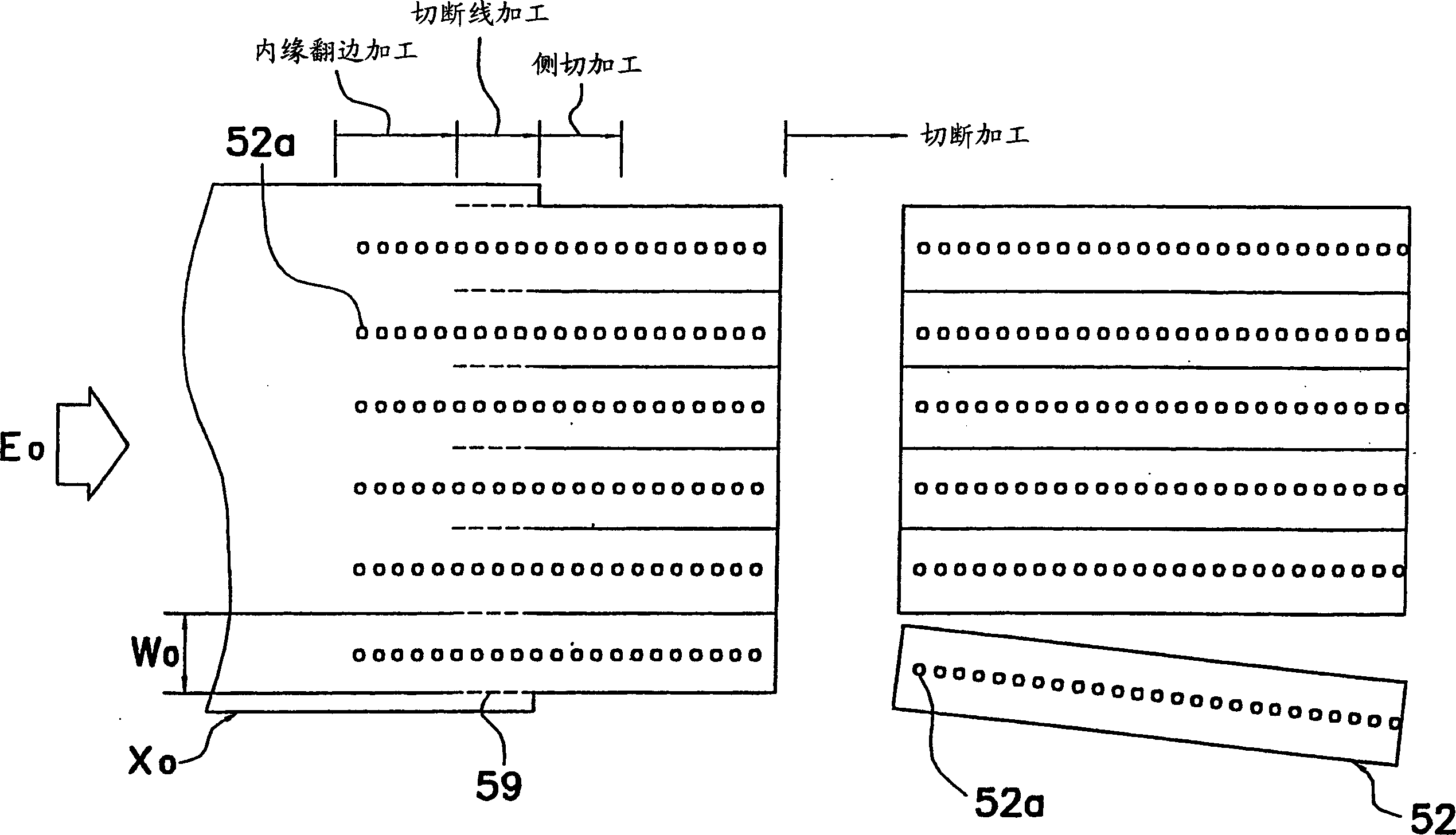
[0038] The heat exchanger 1 includes: a plurality of fins 2 arranged at predetermined intervals in the plate thickness direction; and a plurality of heat transfer tubes 3 attached to penetrate the plurality of fins 2 in the plate thickness direction. Heat sink 2 as Figure 4 and Figure 5 As shown, it has its width from one sid...

no. 2 approach

[0062] In the first embodiment, if Figure 5 As shown, the width of the heat sink 2 is continuously changed, but it can also be as Figure 7 As shown in the heat sink 22, the width is formed stepwise from one side to the other side by W 1 shrink to W 2 shape. Also in this case, the same effect as that of the first embodiment can be obtained.

no. 3 approach

[0064] In the first and second embodiments, such as Figure 5 and Figure 7 As shown, the heat sink 2 is formed in a symmetrical shape with respect to the center (centre) of the width direction of the heat sink, but it may also be Figure 8 Like the heat sink 32 shown, when two heat sinks are arranged in the heat sink width direction, it becomes a rectangular shape. In this case, compared with the first and second embodiments, the material loss of the plate-shaped blank can be further reduced.

[0065] (Other implementations)


PUM


Abstract

The present invention provides a heat exchanger in which the diameter of the heat transfer tube on the liquid side of the heat exchanger is smaller than that of the heat transfer tube on the gas side, while suppressing the reduction of heat transfer efficiency outside the tube and improving the heat transfer efficiency , and the manufacturing method of the heat exchanger adapted thereto. A heat exchanger (1) has: a plurality of fins (2) arranged at predetermined intervals in a plate thickness direction; and a plurality of heat transfer tubes (3) attached so as to pass through the plurality of fins in the plate thickness direction. As shown in Fig. 4 and Fig. 5, the heat sink (2) has a shape whose width continuously decreases from (W1) to (W2) from one side to the other side. The plurality of heat transfer tubes (3) are composed of two or more different diameter tubes, and the large diameter heat transfer tubes are arranged on the upper part of the heat exchanger (1), and the small diameter ones are arranged on the lower part of the heat exchanger (1). heat transfer tube.

Description

technical field [0001] The invention relates to a heat exchanger, a manufacturing method of the heat exchanger and an air conditioner. Background technique [0002] As one type of conventional heat exchangers, there is a cross-fin type heat exchanger. Stretching fin heat exchangers are often used in indoor and outdoor units of air conditioners. As an example, there are figure 1 The L-shaped heat exchanger 51 arranged in the outdoor unit of the air conditioner is shown. [0003] The purpose of the heat exchanger 51 is to communicate with the air flow formed by the propeller blower 61 blowing from the back side to the front side of the outdoor unit casing 62 (see arrow A). 0 and B 0 ) for heat exchange to evaporate or condense the refrigerant flowing inside the tube of the heat transfer tube. [0004] The heat exchanger 51 has a plurality of fins 52 arranged at predetermined intervals in the plate thickness direction, and a plurality of heat transfer tubes 53 attached to p...

Claims


Application Information

Patent Timeline
Patent Type & Authority Applications(China)
IPC IPC(8): F24F1/00F28D1/04F28D1/047F28F1/32F28F13/08
CPCF28D1/0417F28D1/0477F28F1/32F28F13/08F28F2215/00F28F2215/04
Inventor 平良繁治
Owner DAIKIN IND LTD
Why Eureka
Try Eureka