Rotary compressor and control method thereof

A technology of rotary compressor and compression mechanism, applied in rotary piston machinery, rotary piston pump, rotary piston/oscillating piston pump components, etc., can solve the problem of oil viscosity drop, parts wear and compressor failure and other problems, to achieve the effect of reducing oil output, low manufacturing cost and control cost, and preventing the decline of reliability

Active Publication Date: 2011-11-23
GUANGDONG MEIZHI COMPRESSOR
View PDF12 Cites 10 Cited by
  • Summary
  • Abstract
  • Description
  • Claims
  • Application Information

AI Technical Summary

Problems solved by technology

When the refrigerant is injected into the circuit and mixed with liquid refrigerant, the liquid refrigerant will condense in the oil of the compressor, and the viscosity of the oil will drop, which will cause wear of the sliding parts and cause the compressor to fail.

Method used


Image

  • Rotary compressor and control method thereof
  • Rotary compressor and control method thereof
  • Rotary compressor and control method thereof

Examples


no. 1 example

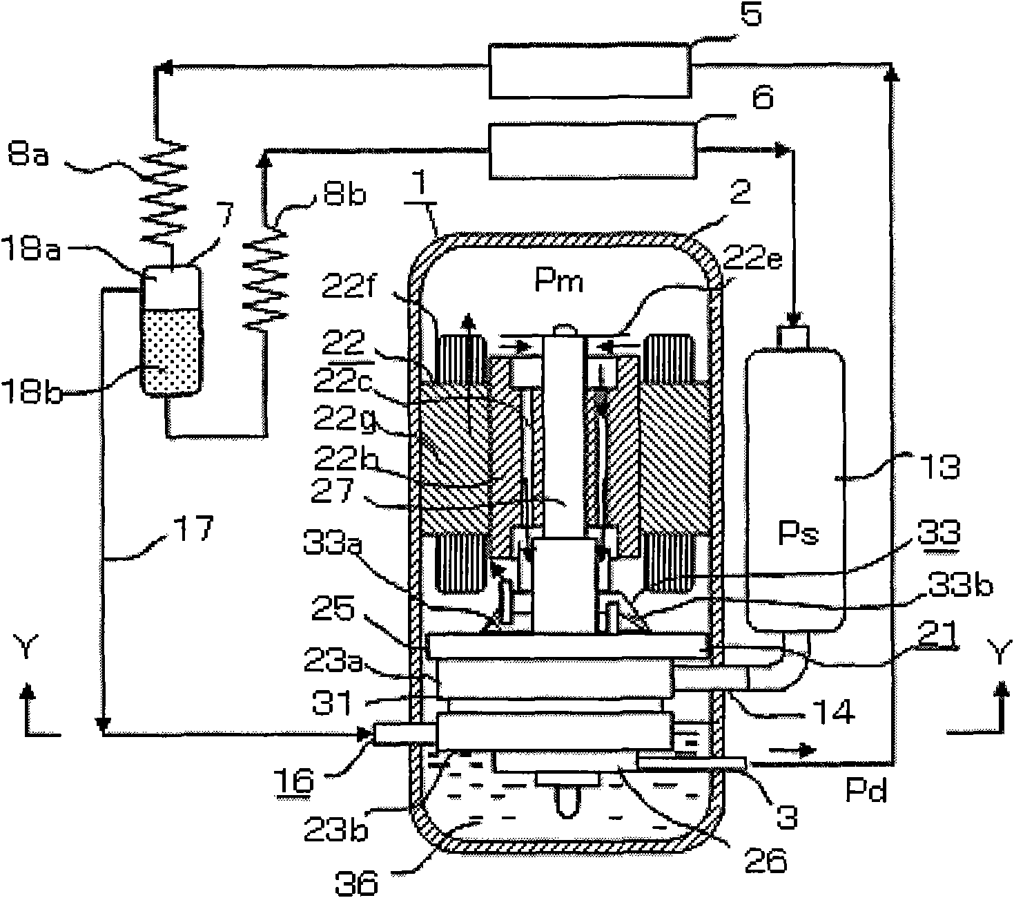
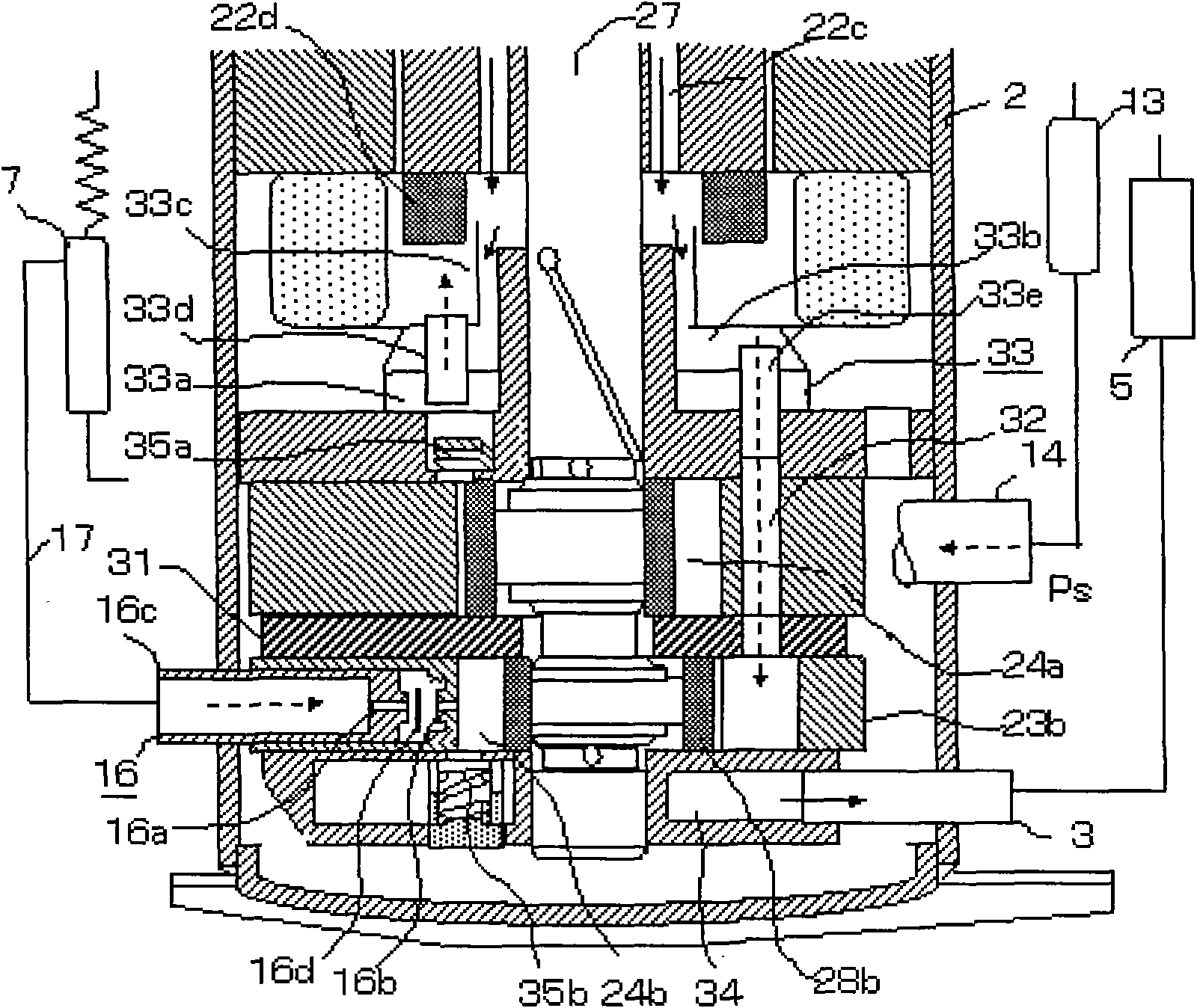
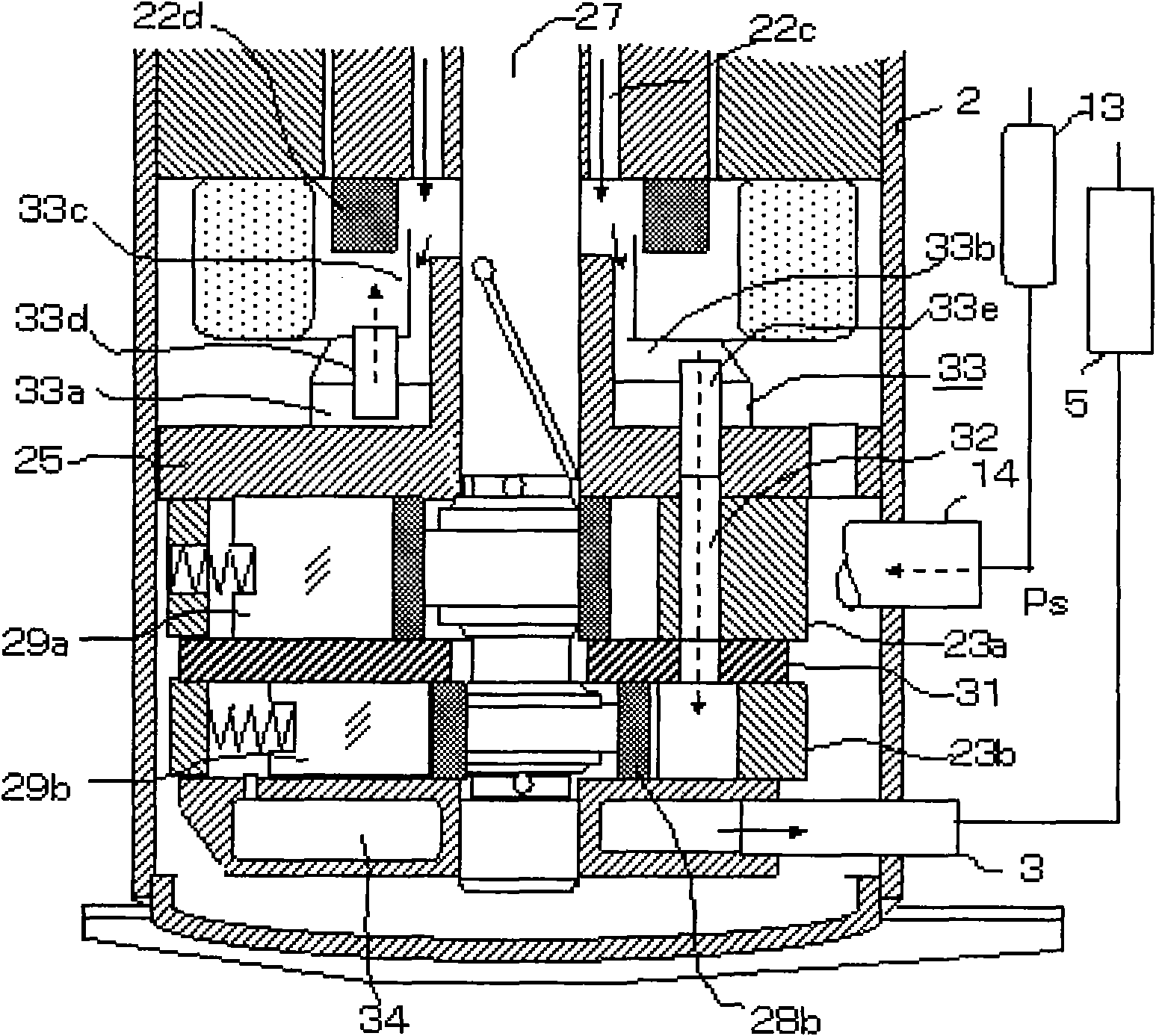
[0029] see figure 1 , is the internal structure of the rotary compressor 1 and the air-conditioning refrigeration cycle equipped with the rotary compressor. figure 2 with image 3 It is a detailed view of the compression mechanism part 21. Figure 4 for figure 1 The Y-Y section diagram in .

[0030] The rotary compressor 1 is composed of a two-stage compression type compression mechanism part 21 mounted on the inner wall of the hermetic casing 2, and a motor part 22 arranged above it.

[0031] The compression mechanism part 21 includes two cylinders: a first cylinder 23a and a second cylinder 23b, a first piston 28a and a second piston 28b housed in the first cylinder compression chamber 24a and the second cylinder compression chamber 24b, and a first slide plate. 29a and the second sliding piece 29b, the main bearing 25 and the sub bearing 26, and the crankshaft 27 supported by the main bearing 25 and the sub bearing 26 are constituted. The intermediate partition 31 san...

no. 2 example

[0067] see Image 6 , by using the U-shaped pipe 41, from the side of the second cylinder 23b suction motor part 22 upper intermediate pressure gas method, can obtain the same effect as the disclosed technology. However, according to this method, the rotor disk cannot be used, so the performance of the oil separator is greatly reduced, and the cost is increased.

[0068] See the first embodiment for the rest of the undescribed parts, and will not repeat them here.

[0069] To sum up, the technology disclosed in the present invention is easy to apply the air injection technology related to the rotary compressor to the system, and has great utilization value in the production business.


PUM


Abstract

The invention relates to a rotary compressor and a control method thereof, and the rotary compressor comprises a motor part and a two-stage compression type compression mechanism part which are arranged in a sealed housing, wherein the motor part comprises a stator and a rotor, the compression mechanism part comprises a first cylinder, a second cylinder, a crankshaft for driving a first piston and a second piston to rotate eccentrically in a first cylinder compression cavity and a second cylinder compression cavity, a main bearing and an auxiliary bearing, the main bearing and the auxiliary bearing are used for supporting the crankshaft, the end parts of a first sliding sheet and a second sliding sheet are connected with the peripheries of the first piston and the second piston respectively, and gas which is spitted from the first cylinder compression cavity into the sealed housing is sucked into the second cylinder compression cavity. A cooling medium injection device communicated with the second cylinder compression cavity is arranged on the second cylinder compression cavity. The rotary compressor has the characteristics of high air-conditioning ability, high efficiency, safety, reliability and a wide application range and can be popularized and applied to heat pump type air conditioners.

Description

technical field [0001] The invention relates to a rotary compressor and a control method thereof. Background technique [0002] The jet air conditioner injects the gas refrigerant generated by the gas-liquid separator into the cylinder compression chamber of the compressor through the refrigerant injection circuit to increase the efficiency. When the refrigerant is injected into the circuit and mixed with liquid refrigerant, the liquid refrigerant will condense in the oil of the compressor, and the viscosity of the oil will decrease, which will cause wear of the sliding parts and cause the compressor to fail. [0003] Patent Document 1: Japanese Laid-Open Patent Publication 2008-286037 Rotary Compressor and Heat Pump System [0004] Patent Document 2: Japanese Laid-Open Patent Publication 2006-177224 Rotary Compressor Contents of the invention [0005] The object of the present invention is to provide a rotary compressor and its control method with simple and reasonable ...

Claims


Application Information

Patent Timeline
Patent Type & Authority Applications(China)
IPC IPC(8): F04C18/356F04C29/12
CPCF04C23/008F04C23/001F04C29/12F04C29/06F04C28/02F04C18/3564
Inventor 小津政雄李华明
Owner GUANGDONG MEIZHI COMPRESSOR
Why Eureka
Try Eureka