Vertical rotary compressor

A vertical rotary compressor technology, applied in the field of rotary compressors, can solve the problems of increased oil discharge, compressor wear failure, oil viscosity reduction, etc., to improve the noise level, improve reliability and efficiency, and reliability problems Improved effect

Active Publication Date: 2014-01-15
GUANGDONG MEIZHI COMPRESSOR
View PDF6 Cites 3 Cited by
  • Summary
  • Abstract
  • Description
  • Claims
  • Application Information

AI Technical Summary

Problems solved by technology

[0004] If a large amount of liquid refrigerant is inhaled during operation, the oil output will increase significantly, and the oil level will also decrease, which will not only cause compressor failure, but also reduce the performance of the heat exchanger
In addition, if the superheat of the oil is insufficient, the viscosity of the oil will be significantly reduced due to the dilution of the condensed refrigerant in the oil, which will lead to wear and tear of the compressor.

Method used


Image

  • Vertical rotary compressor
  • Vertical rotary compressor
  • Vertical rotary compressor

Examples


Embodiment 1

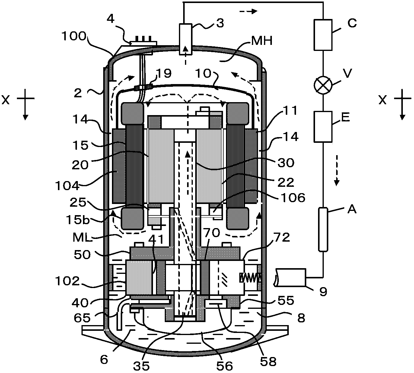
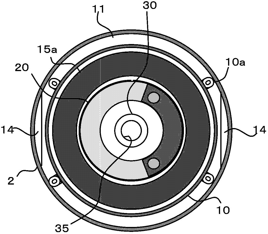
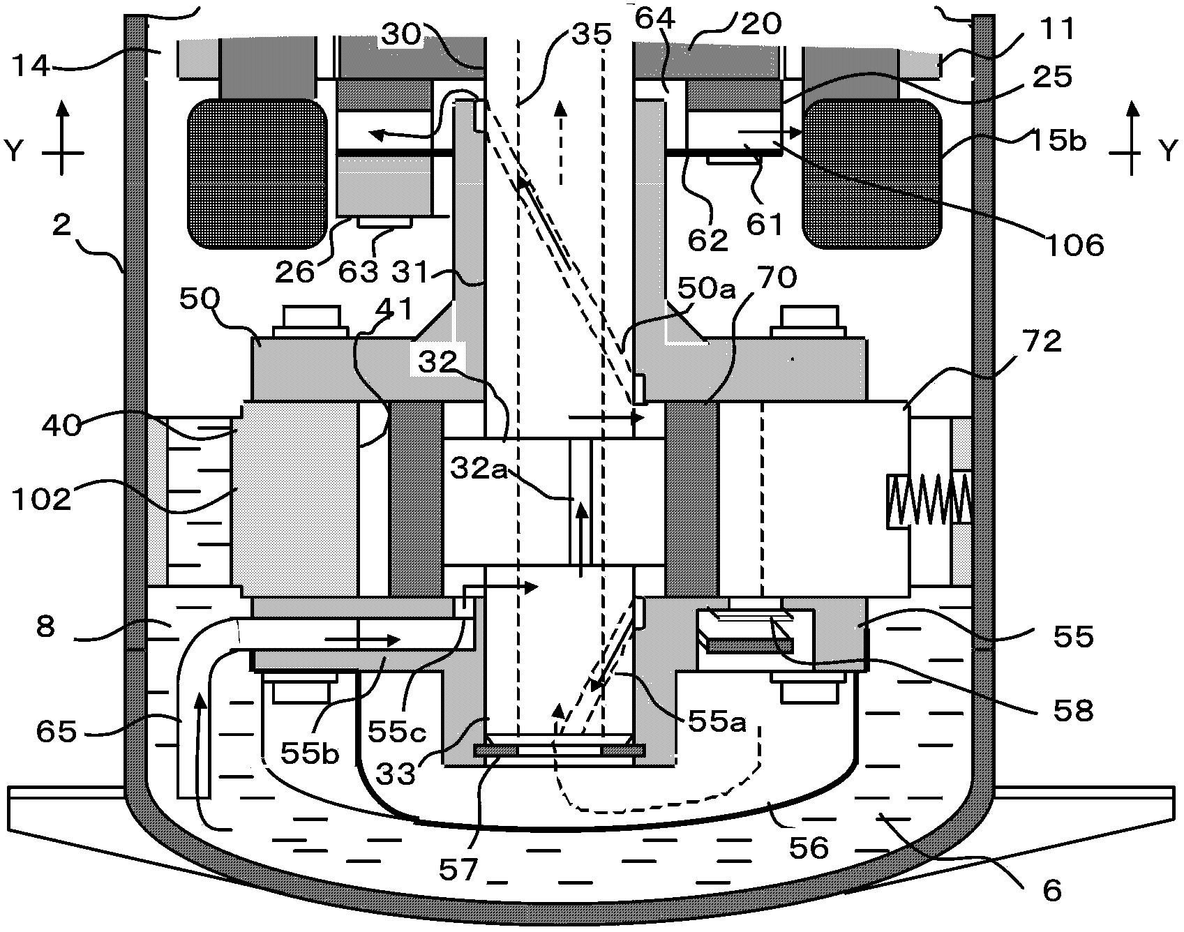
[0047] figure 1 Shown is the basic configuration of the rotary compressor 100 according to the first embodiment and the outline of the refrigeration cycle apparatus connected thereto. The vertical rotary compressor 100 is composed of an electric motor 104 mounted on a hermetic cylindrical casing 2 and a rotary compressor 102 mounted on the lower side thereof, and an oil storage chamber at the bottom of the casing 2 Oil 6 is sealed in 8. The outer peripheries of the motor stator 11 and the compression device 102 are fixed at the inner diameter of the casing 2 . Therefore, the space formed between the motor 104 and the compression device 102 is called an ML cavity.

[0048] The motor 104 is composed of a motor stator 11 equipped with motor windings 15 and a motor rotor 20 fixed to the crankshaft 30 . On the other hand, the compression device 102 is constituted by a piston 70 arranged on the cylinder 40, a vane 72, a crankshaft 30 provided with a shaft through hole, a main bea...

Embodiment 2

[0072] Since the amount of refrigerant flowing in the shaft through hole 35 is the same as the amount of refrigerant discharged from the discharge pipe 3 , the diameter of the shaft through hole 35 only needs to be the same as the inner diameter of the exhaust pipe 3 . However, the diameter of the shaft through hole 35 is limited by the shaft diameter of the crankshaft 30 . Especially in a rotary compressor with a high-speed variable frequency motor or a rotary compressor with a large displacement, if the amount of refrigerant passing through the shaft through hole 35 increases, the compression loss of the compression chamber 41 may increase. Figure 10 The illustrated embodiment 2 is a countermeasure for such exceptional conditions.

[0073] In the compression device 102 , the sub bearing 55 and the main bearing 50 each include an exhaust device 58 , a lower muffler 56 , and an upper muffler 51 . The upper muffler 51 is provided with a muffler exhaust hole 51 a, and the two ...

Embodiment 3

[0079] Figure 12 In the illustrated embodiment 3, the bearing exhaust pipe 53 is used to replace the shaft through hole 35 of the crankshaft 30, so that the high-pressure refrigerant discharged from the compression chamber 41 flows out to the winding through the outer peripheral hole 18 of the iron core provided on the motor stator 11. Cover 10 places. The mixed refrigerant discharged into the winding cover 10 flows through the interior of the motor stator 11 to the ML cavity as in the first embodiment, then flows from the iron core peripheral gap 14 to the MH cavity, and is discharged from the exhaust pipe 3 . Therefore, the same actions and effects as those of Embodiment 1 can be obtained. In addition, in the third embodiment, since the shaft through hole 35 of the crankshaft 30 is not used, a conventional oil supply device can be installed inside the crankshaft 30 . In addition, the motor 104 used in this design is a concentrated winding type variable frequency motor.

...


PUM


Abstract

The invention discloses a vertical rotary compressor. The vertical rotary compressor comprises a sealed housing provided with an exhaust pipe; an electrodynamic machine, a machine winding cover and a rotary compression unit are arranged in the sealed housing; the electrodynamic machine is composed of a motor stator provided with a machine winding, and a motor rotor surrounded by the motor stator; the top of the machine winding is covered by the machine winding cover; the rotary compression unit is arranged under the electrodtnamic machine, and is provided with a compression chamber and a crankshaft. Lubricating oil is stored in the sealed housing; refrigerant discharged from the compression chamber to the machine winding cover flows to a gap between the electrodynamic machine and the rotary compression unit through the inside of the motor stator. The vertical rotary compressor is capable of avoiding compressor reliability reduction caused by discharged oil amount, motor overheating , oil undercooling and the like, and improving efficiency by reducing motor temperature.

Description

technical field [0001] The present invention relates to a rotary compressor applied to an air conditioner, a refrigerating machine, a water heater, etc., in which the internal pressure of the hermetic casing is on the high pressure side. Background technique [0002] Rotary compressors use the internal pressure of the sealed case as the high-pressure side and the crankshaft rotation axis as the vertical direction for reasons such as improving the compression efficiency, lubricating the sliding parts, and reducing the volume of the case by directly sucking the suction refrigerant. , the so-called vertical rotary compressors are widely used. [0003] If the heat exchange between the refrigerant discharged from the compression device and the motor winding is insufficient, the motor winding will not only burn out due to overheating of the motor winding, but also reduce the efficiency of the motor. On the other hand, the comfort in the heating operation mode of the air condition...

Claims


Application Information

Patent Timeline
IPC IPC(8): F04C23/02F04C29/00
Inventor 小津政雄梁自强王玲
Owner GUANGDONG MEIZHI COMPRESSOR
Why Eureka
Try Eureka